Silicon carbide crystal ingot bonding and machining equipment capable of automatically centering and method thereof

A processing equipment, silicon carbide technology, applied in mechanical equipment, material gluing, connecting components, etc., can solve the problems of resource cost waste, processing failure, difficult concentricity, etc., achieve fast and accurate positioning, improve bonding efficiency, and improve adhesion. The effect of combined efficiency

Active Publication Date: 2022-01-21
SUZHOU UKING PHOTOELECTRIC TECH CO LTD
View PDF28 Cites 0 Cited by
  • Summary
  • Abstract
  • Description
  • Claims
  • Application Information

AI Technical Summary

Problems solved by technology

[0004] The existing method of finding the center of the silicon carbide ingot is mainly to place the end surface boss on the end surface of the silicon carbide ingot, and then use a vernier caliper to repeatedly measure the round edge of the silicon carbide ingot at different positions until it is close to the silicon carbide end surface jig The distance from the outer edge, and then slowly correct the end face boss to the center of the silicon carbide crystal ingot, or as mentioned in the sapphire crystal rod sticking process disclosed in the invention patent application publication number CN104131355A, the sapphire crystal rod and the sticky stick boss bonding, but there are many disadvantages in the above process: First, because the round edge of the silicon carbide ingot is irregular before the outer diameter grinding, the method of using the vernier caliper to find the center of the silicon carbide ingot is difficult. The large error is not only inconvenient to operate, but also because the upper and lower end faces of the silicon carbide ingot need to be bonded to the end face fixture, even if the relevant tooling is used, it is difficult to realize the two end face bosses and the upper and lower end faces of the silicon carbide ingot. Maintain consistent concentricity. When the concentricity deviation is too large, the grinding of the outer diameter of the silicon carbide ingot will be uneven during the outer diameter grinding process. Multiple shutdowns are required to repeatedly adjust the position of the silicon carbide ingot and there is a risk of processing failure. , which greatly increases the workload and process time of the staff; secondly, the operator can easily bump into the edge of the silicon carbide ingot during the process of bonding and adjusting the end face boss, causing edge chipping or falling, causing the silicon carbide ingot to break and be scrapped , resulting in a waste of resource costs

Method used


Image

  • Silicon carbide crystal ingot bonding and machining equipment capable of automatically centering and method thereof
  • Silicon carbide crystal ingot bonding and machining equipment capable of automatically centering and method thereof
  • Silicon carbide crystal ingot bonding and machining equipment capable of automatically centering and method thereof

Examples


Embodiment 1

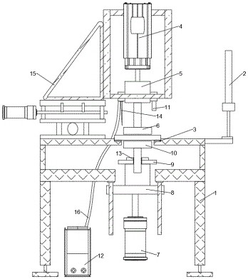
[0035] Such as figure 1 As shown, a silicon carbide ingot bonding processing equipment that can be automatically centered includes a machine body 1, an industrial computer 2, a ring-shaped workbench 3 fixed on the machine body 1, and a sliding connection to the machine body. The telescopic cylinder 4 on 1, the first clamping mechanism 5 fixedly connected to the telescopic cylinder 4, the first bonding jig 6 connected to the first clamping mechanism 5, and the lifting module fixed on the machine body 1 7. The second clamping mechanism 8 fixedly connected with the lifting module 7, the positioning plate 9 installed on the second clamping mechanism 8, the second bonding jig 10 connected to the second clamping mechanism 8, and the second A distance measuring sensor 11 fixedly connected to a clamping mechanism 5, a bonding wax spray device 12 arranged on the machine body 1, a needle-shaped bonding wax spray head 14 fixedly connected to the first clamping mechanism 5, a horizontal d...

Embodiment 2

[0043] Different from Embodiment 1, the center of the machine body 1 can be provided with a ladder-shaped building groove, and the workbench 3 is fixed on the machine body 1 in a stacked manner, which is convenient for the lifting module 7 to drive the second bonding process. The tool 10 moves up and down through the workbench 3, and the workbench 3 of different sizes can be replaced according to the size of the silicon carbide ingot. The workbench 3 enables the silicon carbide ingots of different sizes to be placed on the machine body 1 smoothly. In the example, a 6-inch positioning flat plate 9 is selected, and the positioning hole 13 provided thereon has a size of 130mm, which is used to support a 6-inch silicon carbide crystal ingot.

[0044] The first clamping mechanism 5 and the second clamping mechanism 8 are centering chucks, which can be pneumatic three-jaw or four-jaw chucks, and are used to clamp the first bonding fixture 6 or the second bonding fixture 10 the end. ...

Embodiment 3

[0047] A method for bonding silicon carbide crystal ingots that can be automatically centered, using the equipment in Embodiment 2, comprising the following steps:

[0048] S1. Assemble and inspect silicon carbide ingot bonding processing equipment

[0049] S11. Check whether the telescopic cylinder 4, the first clamping mechanism 5, the lifting module 7, and the second clamping mechanism 8 are operating normally;

[0050] S12. Fixing the first bonding jig 6 with the first clamping mechanism 5 is equivalent to fixing the first bonding jig 6 with the telescopic cylinder 4;

[0051] S13. Select a 6-inch positioning plate 9 and install it on the second clamping mechanism 8, and set the end of the second bonding jig 10 in the positioning round hole 13 to realize the fixing of the center of the second bonding jig 10 , and then use the second clamping mechanism 8 to clamp the second bonding jig 10;

[0052] S14. Check whether the silicon carbide ingot bonding processing equipment ...


PUM


Abstract

The invention provides silicon carbide crystal ingot bonding and machining equipment capable of automatically centering and a method thereof and belongs to the technical field of bonding of silicon carbide crystal ingots. The silicon carbide crystal ingot bonding and machining equipment comprises a machine body and further comprises an industrial personal computer, a workbench, a telescopic cylinder, a first clamping mechanism, a first bonding jig, a lifting module, a second clamping mechanism, a positioning flat plate, a second bonding jig, a distance measuring sensor and a bonding and wax spraying device. The invention relates to silicon carbide crystal ingot bonding and machining equipment capable of automatically centering. The equipment comprises the distance measuring sensor; the distance measuring sensor is used for measuring the centers and the edge contours of silicon carbide crystal ingots after grinding the end surfaces and carrying out two-dimensional curve modeling; the centers of the silicon carbide crystal ingots can be automatically, quickly and accurately found; and fitting calculation of size circles required by bonding can be carried out.

Description

technical field [0001] The invention relates to a silicon carbide crystal ingot bonding processing device and method capable of automatic centering, and belongs to the technical field of silicon carbide crystal ingot bonding. Background technique [0002] Silicon carbide is an important third-generation semiconductor material developed after the first-generation semiconductor Si, the second-generation semiconductor GaAs or InP, etc. It has wide band gap, high thermal conductivity, high breakdown field strength, and high carrier The characteristics of saturation migration rate have irreplaceable advantages in high temperature, high frequency, high power, microelectronic devices and other extreme environments such as aerospace, military industry, and nuclear energy, and have huge application potential. [0003] The production of a complete silicon carbide substrate requires many processes to be processed. The outer diameter grinding of the silicon carbide ingot is one of the m...

Claims


Application Information

Patent Timeline
Patent Type & Authority Applications(China)
IPC IPC(8): B05B13/04F16B11/00
CPCB05B13/04F16B11/006
Inventor 刘聚斌陈建明周元辉刘春艳杨洪雨
Owner SUZHOU UKING PHOTOELECTRIC TECH CO LTD
Why Eureka
Try Eureka