Wellhead hoisting device

A hoisting device and winding technology, which is applied in the direction of hoisting device, portable lifting device, drilling equipment, etc., can solve the problems of small limited range, limited vertical height adjustment, and high cost investment

Active Publication Date: 2022-01-21
CHINA PETROLEUM & CHEM CORP +1
View PDF6 Cites 0 Cited by
  • Summary
  • Abstract
  • Description
  • Claims
  • Application Information

AI Technical Summary

Problems solved by technology

Due to the limited piston stroke, it is impossible to install and vertically place too long or heavy anti-nozzle pipes, the limited range is small, and it is not convenient to increase or decrease the length of the anti-nozzle pipes. In addition, the hydraulic cylinder and the anti-nozzle pipe are arranged asymmetrically eccentrically , poor stability, security risks and other defects
[0008] The above-mentioned several devices have more or less various defects, mainly due to small lifting weight, limited vertical height adjustment, and large restrictions due to the operating conditions of the well site. In addition, in addition to the crane, the other two devices Both are only applicable to the hoisting of the lubricator. For other equipment that needs to be hoisted at the wellhead, additional hoisting equipment is required, resulting in high cost investment

Method used


Image

  • Wellhead hoisting device
  • Wellhead hoisting device
  • Wellhead hoisting device

Examples


Embodiment 2

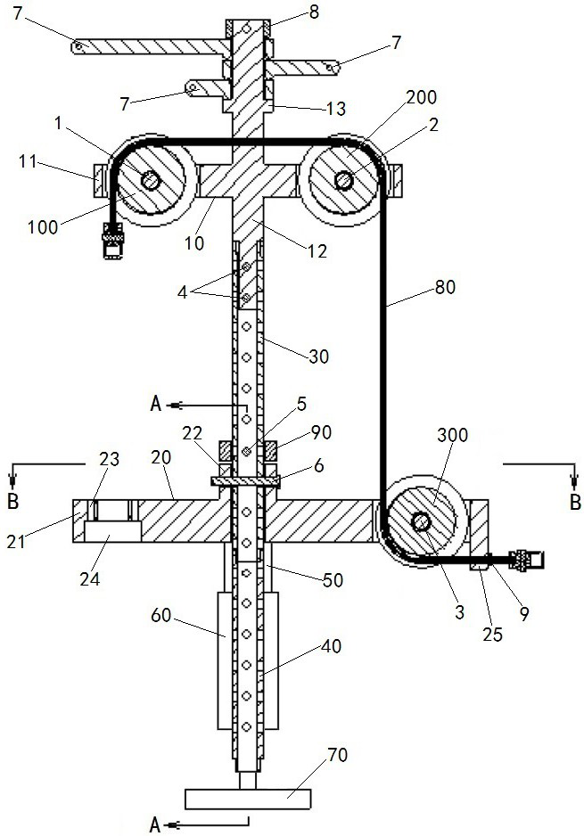
[0075] Embodiment 2 of the wellhead hoisting device in the present invention: the difference from the above-mentioned embodiment is that the blowout prevention pipe string may not be connected on the ground and directly connected to the traction rope as a whole, but may be connected to a When installing a blowout preventer, connect a section of the blowout preventer with the traction rope, and then continue to connect the blowout preventer with the continuous rise of the pulley frame, so that the blowout preventer string is continuously added to the blowout preventer connection during the rising process made.

Embodiment 3

[0076] Embodiment 3 of the wellhead hoisting device in the present invention: the difference from the above-mentioned embodiments is that the equipment to be hoisted can be other equipment that needs to be installed at the wellhead except the blowout pipe.

[0077] Embodiment 4 of the wellhead hoisting device in the present invention: the difference from the above embodiment is that the stabilizing rod fixed on the top of the pulley frame can be welded or screwed on the top of the pulley frame.

Embodiment 5

[0078] Embodiment 5 of the wellhead hoisting device in the present invention: the difference from the above embodiments lies in that the number of stabilizing rods can be only two or more.

[0079] Embodiment 6 of the wellhead hoisting device in the present invention: the difference from the above embodiments lies in that the connecting column of the pulley frame is screwed to the top of the uppermost bearing rod.


PUM


Abstract

The invention provides a wellhead hoisting device. The wellhead hoisting device comprises a bearing bracket, a pulley yoke, a telescopic power unit, a bearing rod, a first plug pin and a second plug pin; the pulley yoke is arranged at the top of the bearing bracket; the bearing bracket comprises a bearing plate, a bearing lifting block arranged above the bearing plate and support legs; the telescopic power unit comprises a cylinder and a telescopic rod, the upper end of the cylinder is fixed to the bearing plate, the lower end of the cylinder is fixed to the supporting legs, and the telescopic rod penetrates through the bearing plate to be matched with the bearing lifting block in a pushing mode; the bearing rod penetrates through the bearing plate and the bearing lifting block, and a first through hole and a second through hole are formed in the bearing rod; the first plug pin penetrates through the bearing lifting block and the first through hole; the second plug pin penetrates through the bearing plate and the second through hole; only the first plug pin and the second plug pin are installed alternately, the telescopic rod controls the bearing lifting block to move up and down, the first plug pin drives the bearing rod to rise intermittently and is connected with the next section of bearing rod after a certain distance, and operation is repeated till a bearing rod string with a certain height is formed. The wellhead hoisting device is wide in application range, large in lifting weight and small in limitation of well site conditions, and vertical height adjustment is facilitated.

Description

technical field [0001] The invention relates to the technical field of auxiliary equipment for petroleum exploitation, in particular to a wellhead hoisting device. Background technique [0002] When oil and gas production wells are tested, the prior art generally uses three methods of crane, rotary lifting device and vertical lifting system to realize the installation or discharge of the lubricator. [0003] Among them, the installation of the crane is to first connect the lubricator string on the ground, and hang one end of the lubricator string with a crane hook to erect it to complete the installation or discharge of the lubricator. However, when the well site environment is poor, there is a crane Defects such as inability to reach the wellhead, limited telescopic length, and high cost of use. [0004] The Chinese utility model patent with the authorized notification number CN204457528U discloses a nozzle installation device, which belongs to a rotary lifting device. Th...

Claims


Application Information

Patent Timeline
Patent Type & Authority Applications(China)
IPC IPC(8): B66D3/06B66D3/08E21B23/00E21B19/00
CPCB66D3/06B66D3/08E21B23/00E21B19/00B66D2700/028
Inventor 钟仲良褚红玉刘晓玲惠小敏杨明滔黄仕勇唐莉李萍
Owner CHINA PETROLEUM & CHEM CORP
Why Eureka
Try Eureka