
Sleeve grouting reinforcing steel bar interlocking joint and full-prefabrication construction method for shear wall through sleeve grouting reinforcing steel bar interlocking joint

A sleeve grouting and shear wall technology, which is applied to walls, buildings, building reinforcements, etc., can solve the problems of high cost of joints, not dense grouting, and difficult grouting, etc., and achieve the goal of improving construction efficiency and improving prefabricated assembly rate Effect

Pending Publication Date: 2022-01-21
TONGJI UNIV +2
View PDF4 Cites 0 Cited by
  • Summary
  • Abstract
  • Description
  • Claims
  • Application Information

AI Technical Summary

Problems solved by technology

At the same time, the reserved steel bars should also be accurately positioned during the construction process, and the allowable error is at the millimeter level, which causes great inconvenience to the manual-led on-site construction
[0020] When there are many steel bar joints, it is likely that the steel bars cannot be inserted into the sleeve at the same time. In this way, the position of the reserved steel bars needs to be adjusted. When the error is large, the reserved steel bars may be bent at 90 degrees to insert the sleeve, which cannot In extreme cases, the steel bar that cannot be inserted into the sleeve will be cut off, which will leave a safety hazard
[0021] 2) Grouting is not easy to compact
[0022] At present, the grouting sleeve butt joint used in the prefabricated assembly structure is small in diameter, and the gap between the steel bar and the sleeve wall is small, which is prone to grouting defects and makes the grouting not dense. If the grouting material is not dense, the reliable force transmission of the joint cannot be guaranteed. , will leave a great security risk
[0023] 3) The cost of joints is high
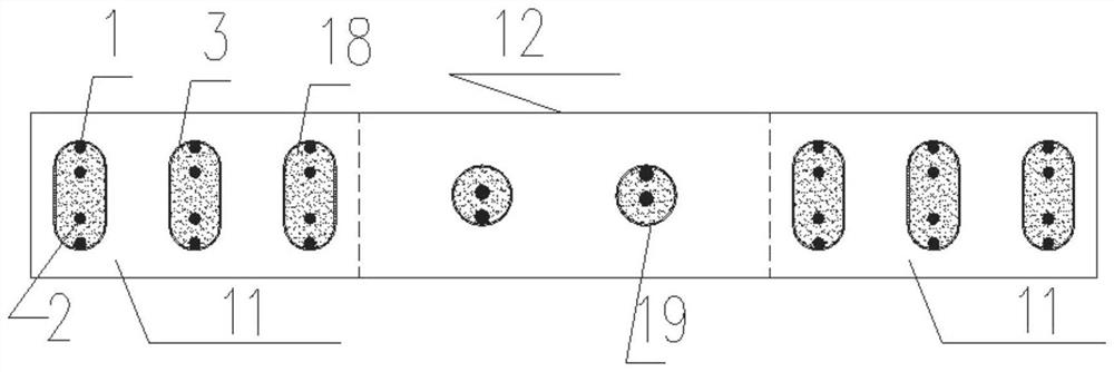
[0026] At present, the existing prefabricated shear walls are generally not fully prefabricated. The edge members 11 at both ends can only be cast-in-place structures, and the middle wall 12 is prefabricated. Because the edge members have many steel bars, the existing set in Example 1 If the diameter of the cylinder is small, multiple steel bars are inserted into the sleeve with a small diameter at the same time. The construction is difficult, and the steel bars will not be inserted into the sleeve on site, and the steel bars will be cut off, which becomes a safety hazard. It is not easy to pour densely, and the reliability of steel joints is difficult to guarantee
[0027] Therefore, the prefabricated shear wall is not fully prefabricated. There are cast-in-situ sections of edge components and wet work, and the concrete needs to be poured and rammed, so that the advantages of the prefabricated assembly structure cannot be fully reflected.

Method used


Image

  • Sleeve grouting reinforcing steel bar interlocking joint and full-prefabrication construction method for shear wall through sleeve grouting reinforcing steel bar interlocking joint
  • Sleeve grouting reinforcing steel bar interlocking joint and full-prefabrication construction method for shear wall through sleeve grouting reinforcing steel bar interlocking joint
  • Sleeve grouting reinforcing steel bar interlocking joint and full-prefabrication construction method for shear wall through sleeve grouting reinforcing steel bar interlocking joint

Examples


Embodiment 1

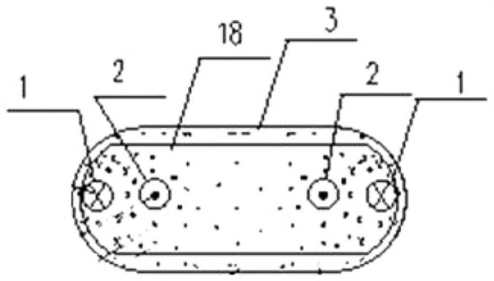
[0090] Such as figure 2 Shown: a sleeve grouted steel bar interlocking joint, mainly used for the connection of steel bars in the edge members of prefabricated shear walls, which includes two sets of first steel bar 1 and second steel bar 2 with opposite directions of force, for example and not limitation , there are two steel bars in each group, and four steel bars are placed in an oval sleeve 3, wherein the two first steel bars 1 are respectively connected to the inner walls of both sides of the sleeve 3 by spot welding, and the two first steel bars 1 are The upper part protrudes upwards along the inner wall of the sleeve 3, the two second steel bars 2 are placed in the lower part of the sleeve 3 and are respectively located inside the two first steel bars 1, and the lower parts of the two second steel bars 2 protrude toward the lower part of the sleeve 3; The lower part of the sleeve 3 is provided with a sleeve grouting port 4, and the upper part of the sleeve 3 is provide...

Embodiment 2

[0122] By way of example and not limitation, this embodiment provides a specific implementation of the interlocking joint of four steel bars grouted in a cylinder, in order to analyze and demonstrate the feasibility, performance and effect of the interlocking joint of this application.

[0123] (1), composition of grouting sleeve self-locking joint

[0124]a) Sleeve 3. The sleeve is generally composed of two circular arcs and a rectangle. The sleeve is processed by hot-rolling steel plates. The inner and outer walls do not need to be processed, and the cost is low. Considering the convenience of construction and the constraints of the sleeve, the optimal shape of the sleeve is shown in Figure 15. By increasing the thickness of the sidewall on the long side of the sleeve, the sleeve constraint is increased, which is unique to this application.

[0125] When the diameter of the steel bar is 12, 14, 16, 18, 20mm, the length of the sleeve can be increased by 2d-3d, and the transv...

Embodiment 3

[0156] Such as image 3 , 4 , 5, 18 A fully prefabricated construction method for a shear wall, the above-mentioned interlocking joint is applied to the edge member 11 of the shear wall, so that the prefabricated assembled shear wall is a fully prefabricated component, the prefabrication rate is improved, and the shear force is avoided. Wet work on the wall speeds up the construction progress. The specific steps are as follows:

[0157] The first step: the factory makes the upper shear wall 7, the upper shear wall 7 includes the edge member 11 of the shear wall and the wall body 12 of the shear wall, and the wall body 12 of the shear wall is provided with a prefabricated wall body sleeve 28. The prefabricated wall body sleeve 28 is provided with a prefabricated wall middle steel bar joint 19, a prefabricated wall middle and upper shear wall steel bar 26, and a prefabricated wall middle and lower shear wall middle steel bar 27;

[0158] The second step: make some sleeves 3, w...


PUM

PropertyMeasurementUnit
Thicknessaaaaaaaaaa

Abstract

The invention relates to a sleeve grouting reinforcing steel bar interlocking joint and a full-prefabrication construction method for a shear wall through the sleeve grouting reinforcing steel bar interlocking joint. The interlocking joint is mainly used for connecting reinforcing steel bars in edge members of the prefabricated shear wall, and comprises two groups of first reinforcing steel bars and second reinforcing steel bars, the stress directions of the first reinforcing steel bars and the second reinforcing steel bars are opposite, and the reinforcing steel bars are arranged in an oval sleeve. The two first reinforcing steel bars are connected to the inner walls of the two sides of the sleeve through spot welding respectively, the upper portions of the two first reinforcing steel bars extend upwards along the inner walls of the sleeve, the two second reinforcing steel bars are arranged on the lower portion in the sleeve and located on the inner sides of the two first reinforcing steel bars respectively, and the lower portions of the two second reinforcing steel bars extend towards the lower portion of the sleeve; a sleeve grouting opening is formed in the lower portion of the sleeve, and a sleeve grout outlet is formed in the upper portion of the sleeve. According to the full-prefabrication construction method of the shear wall, the interlocking joint is applied to an edge component of the shear wall, so that full prefabrication of the shear wall is achieved, and the construction efficiency is improved.

Description

technical field [0001] The invention relates to the technical field of prefabricated buildings, in particular to sleeve grouting reinforcement interlocking joints and a fully prefabricated construction method for shear walls. Background technique [0002] In recent years, with the acceleration of urbanization and the continuous expansion of urban infrastructure construction, the contradiction between insufficient resource supply and massive energy consumption has become increasingly prominent, the situation of ecological civilization construction and environmental protection has become more and more severe, and the extensive development of the traditional construction industry The way can no longer meet the requirements of social development, and the difference between the construction of ecological civilization in the field of construction and the implementation of the development concept of green cycle and low carbon is getting bigger and bigger. The development of the cons...

Claims


Application Information

Patent Timeline
IPC IPC(8): E04C5/16E04C5/18E04B2/56
CPCE04C5/165E04C5/18E04B2/56
Inventor 余琼白少华范宝秀张志董经民陈振海马永宣孙佳秋
Owner TONGJI UNIV
Learn More