
Casting method of hydraulic casting

A casting and hydraulic technology, applied in the field of casting casting, can solve the problems of insufficient processing roughness, liquid leakage, unsatisfactory control of steps and parameters, etc.

Pending Publication Date: 2022-01-25
宁波拓铁机械有限公司
View PDF10 Cites 2 Cited by
  • Summary
  • Abstract
  • Description
  • Claims
  • Application Information

AI Technical Summary

Problems solved by technology

The processing roughness of the casting valve body mounting surface is Ra1.6μm, which is extremely demanding. At the same time, it must meet the hydraulic pressure requirements of 40Mpa. The castings must not leak or seep, which cannot be achieved by conventional casting methods; the hydraulic chambers of the hydraulic castings and The installation hole of the valve body is formed by a sand core. Specifically, the sand core is directly made of chromite sand through an adhesive. This structure will have problems such as insufficient sand mold strength and uneven cooling during the pouring process. During the pouring process, there may be phenomena such as sand loss on the surface structure, which will affect the structure of the hydraulic cavity and the installation hole of the valve body. The structure is not dense enough or casting defects such as pores and slag inclusions appear, resulting in processing roughness that cannot reach Ra1.6μm and leakage, seepage problem
[0005] In addition, in the existing casting process of the above-mentioned castings, due to the unsatisfactory control of the feeding port of the gating system and the steps and parameters of the entire casting process, it is easy to cause the occurrence of gas circles and slag inclusion defects in the castings.

Method used

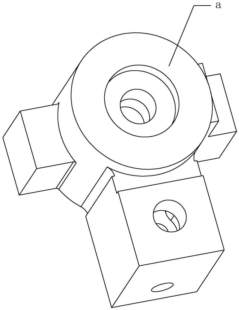
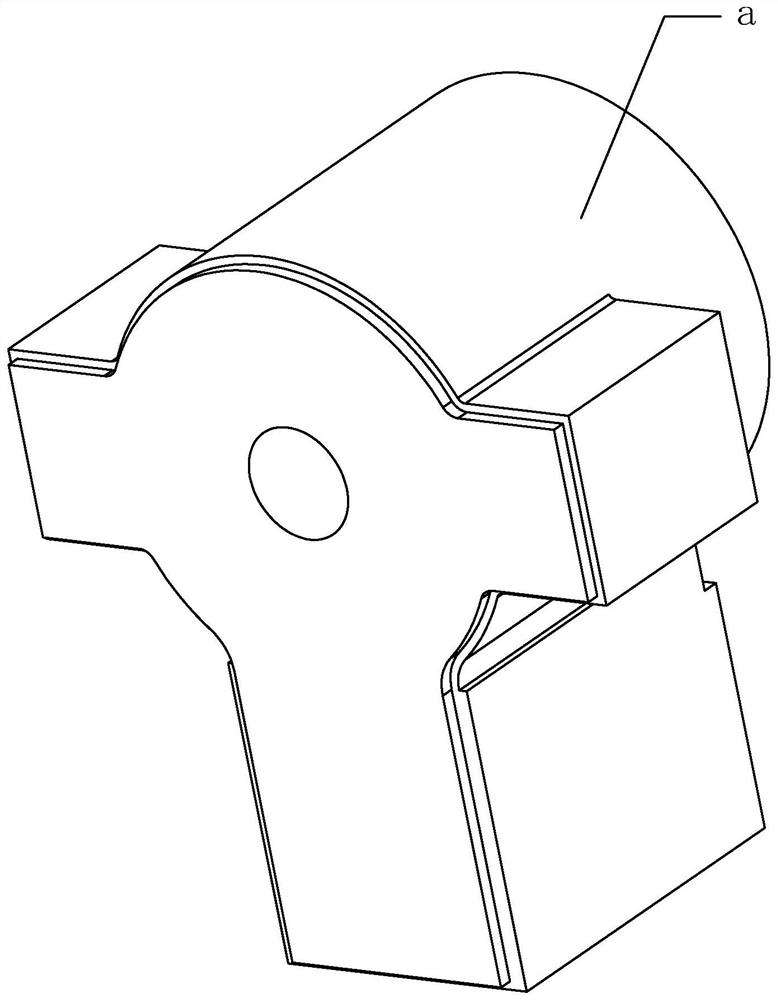
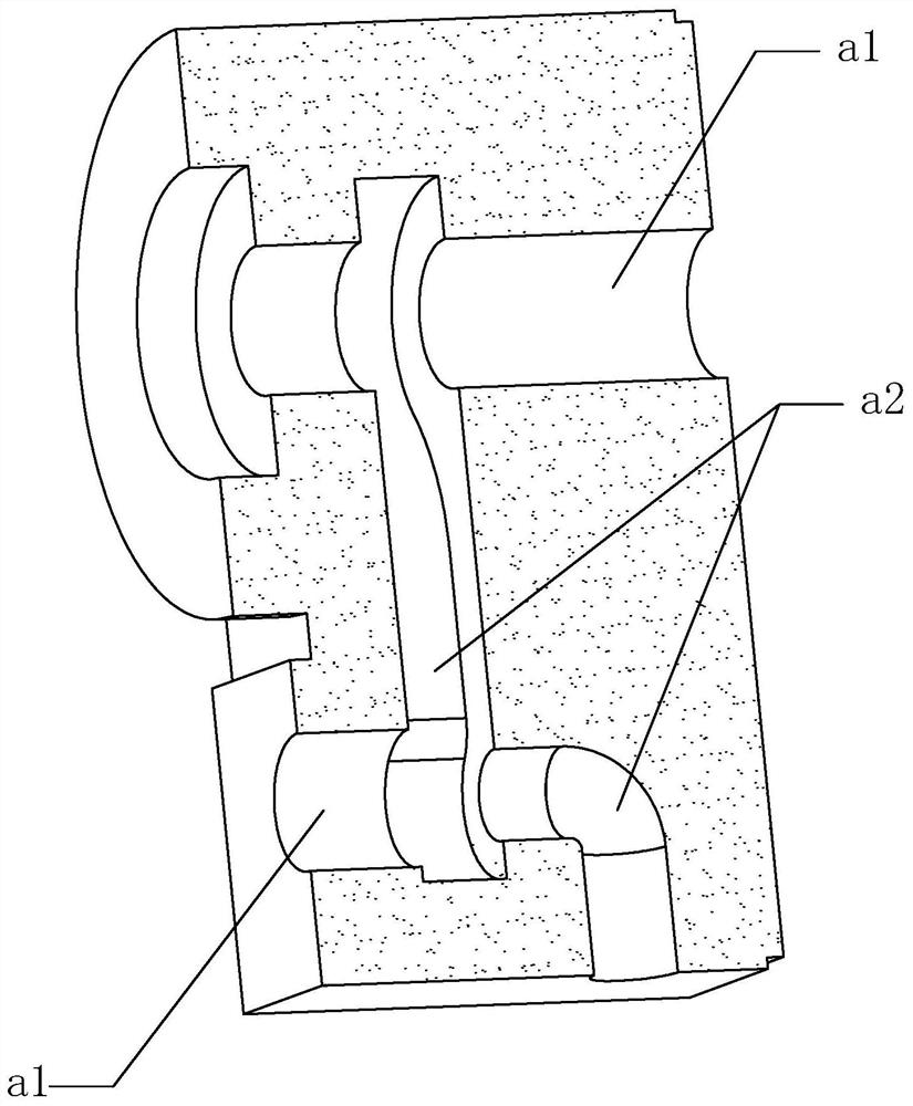

Image

  • Casting method of hydraulic casting
  • Casting method of hydraulic casting
  • Casting method of hydraulic casting

Examples


Embodiment 1

[0047] (1) The raw material of following mass percentage is taken: 40% of pig iron, steel scrap 35%, 25% of returned charge, carburizer: 0.9% of the total amount of pig iron, scrap steel, returned charge;

[0048] (2) Put all the pig iron and steel scrap into the smelting furnace, and then add a carburant with a total amount of 0.9% of the formula; heat to melt the charge, and add FeMn65 ferromanganese and FeSi75 ferromanganese after the charge is melted, and ferromanganese The amount is 0.25% of the total mass of pig iron, scrap steel and returned materials, and the addition of ferrosilicon is 0.7% of the total mass of pig iron, scrap steel and returned materials to obtain the original molten iron, which is continuously heated to 1453 ° C; the obtained The composition and mass percentage of the original molten iron are C3.50%, Si1.46%, Mn0.42%, P0.027%, S0.017%, and the rest is iron;

[0049] (3) The spheroidization is carried out by the flushing method. The spheroidizing age...

Embodiment 2

[0059] (1) The raw materials of the following mass percentages are weighed: 35% of pig iron, 35% of steel scrap, 30% of recharge, recarburizer: 1.0% of the total amount of pig iron, scrap, and recycle;

[0060] (2) Put all the pig iron and scrap steel into the smelting furnace, and then add a carburant with a total formula of 1.0%; heat to melt the charge, and add FeMn65 ferromanganese and FeSi75 ferromanganese after the charge is melted, and ferromanganese The amount is 0.27% of the total mass of pig iron, scrap steel and returned materials, and the addition of ferrosilicon is 0.55% of the total mass of pig iron, scrap steel and returned materials to obtain the original molten iron, which is continuously heated to 1475 ° C; the obtained The composition and mass percentage of the original molten iron are C3.55%, Si1.50%, Mn0.41%, P0.024%, S0.019%, and the rest is iron;

[0061](3) The spheroidization is carried out by the flushing method. The spheroidizing dam on one side of t...


PUM

PropertyMeasurementUnit
Particle sizeaaaaaaaaaa
Thicknessaaaaaaaaaa

Abstract

A casting method of a hydraulic casting comprises the steps that (1) sand mold manufacturing is conducted, specifically, a casting system of the hydraulic casting is cast through molding sand, the casting system comprises a casting cavity and a pouring system, and a sand core is arranged in the casting cavity to form a hydraulic cavity of the casting and a valve body mounting hole; (2) a burdening process is carried out; (3) a smelting process is carried out; (4) a spheroidizing process is carried out; (5) an inoculation process is carried out; and (6) a pouring process is carried out, specifically, when the temperature is reduced to 1280-1330 DEG C, molten iron is poured into the casting system to form the casting; metal-stream inoculation is conducted through inoculation powder while pouring is conducted, the adding amount is 0.08%-0.10% of the total amount of the original molten iron, the inoculation powder is a silicon-barium inoculant, and the silicon-barium inoculant comprises, by mass, 69%-74% of Si, 0.5%-2.0% of Ca, 1.5%-2.5% of Ba, 2%-2.5% of Al, smaller than or equal to 0.02% of S and the balance iron; and after the casting is cooled, the hydraulic casting is obtained. The scheme provided by the invention has the advantages that the defects of ring gas and slag inclusions of the hydraulic casting can be effectively improved, and the phenomena such as sand falling of a surface structure cannot occur in the pouring process.

Description

technical field [0001] The present application relates to the technical field of casting castings, in particular to a casting method of hydraulic castings. [0002] technical background [0003] Die-casting machine is a machine used for pressure casting. Under the action of pressure, the die-casting machine hydraulically injects the molten metal into the mold for cooling and forming. After the mold is opened, solid metal castings can be obtained. It is initially used for die-casting letters, etc.; the die-casting machine provides The main source of pressure is the hydraulic system, which requires the use of hydraulic castings. The use conditions of hydraulic castings in die-casting machines are very demanding, such as high mechanical properties, and cracks, cold shuts, shrinkage cavities, looseness, slag inclusions, etc. are not allowed Defects, so the casting process requirements for hydraulic castings are very high. as attached Figure 1-3 The structure shown is a typical ...

Claims


Application Information

Patent Timeline
IPC IPC(8): B22C9/02B22C9/08C22C33/10C22C37/04C22C37/10B22C9/10B22C9/24
CPCB22C9/02B22C9/082B22C9/086C22C33/10C22C37/04C22C37/10B22C9/106B22C9/24
Inventor 宋泽锴项铮宇吴超宋贤发徐莉雄周宁宋寅进
Owner 宁波拓铁机械有限公司
Learn More