Gas conveying pipe punching process for gas appliance

A technology for gas transmission pipes and gas appliances, which is applied in manufacturing tools, metal processing equipment, feeding devices, etc., can solve the problems of insufficient punching effect, short service life of punching needles, difference in spacing between adjacent holes, etc., so as to improve the effect of punching force. , The effect of high punching efficiency and avoiding errors

Pending Publication Date: 2022-01-28
XINCHANG GREAT WALL AIR CONDITION PARTS
View PDF0 Cites 0 Cited by
  • Summary
  • Abstract
  • Description
  • Claims
  • Application Information

AI Technical Summary

Problems solved by technology

The gas pipeline in the gas cooker is a porous pipeline, which is punched and formed by stamping technology. The following defects exist in the punching process: 1. Each time a hole is punched, the gas pipeline needs to be manually moved and re-fixed, which is labor-intensive. The production efficiency is low, the distance between adjacent holes is different, the error is large, and the product quality is low; 2. For gas pipelines with

Method used


Image

  • Gas conveying pipe punching process for gas appliance
  • Gas conveying pipe punching process for gas appliance
  • Gas conveying pipe punching process for gas appliance

Examples


Embodiment Construction

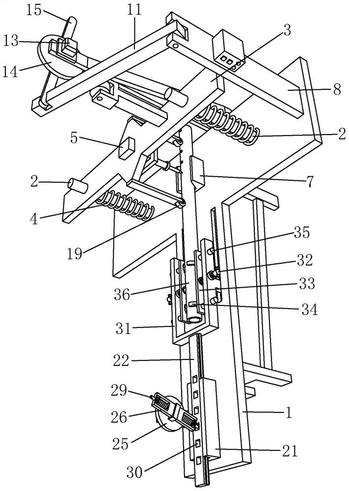
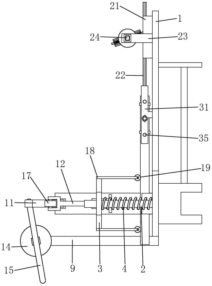
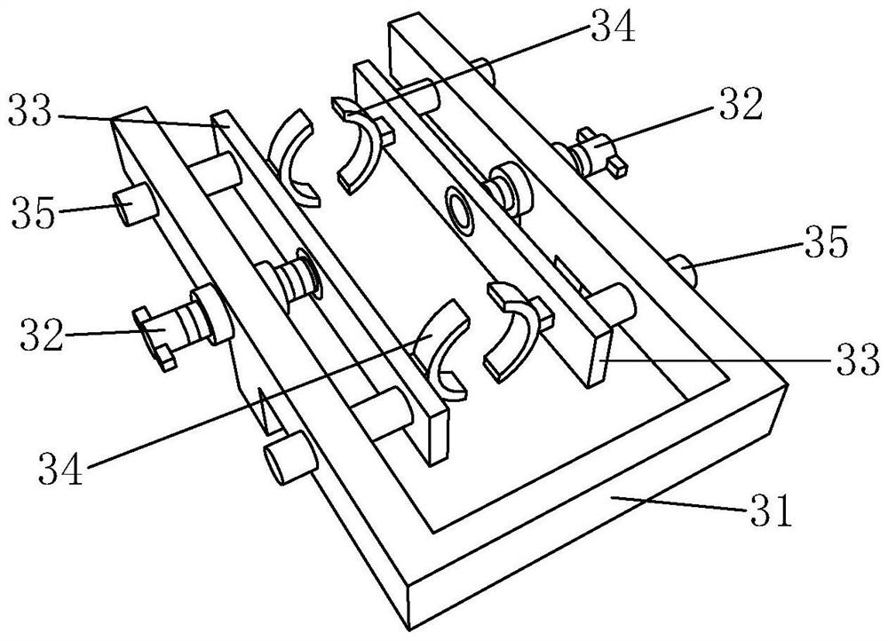
[0037] like Figure 1 to 5As shown, the punching device for the punching process of the present invention includes a table 1 and a pressure plate 3, and the strip 1 is symmetrically distributed, and the guide column 2 passes through the pressure plate 3, the table 1 and the pressure plate 3. There is a compressive spring 4, and the compression spring 4 is provided in the guide post 2, and a punching mechanism is provided on the pressure plate 3, and the punching mechanism includes a stroke cylinder 5 and a punch 6, and the stroke cylinder 5 is disposed on the pressure plate 3, and the needle 6 On one end of the piston rod of the stroke cylinder 5, the stroke cylinder 5 is pulled by the punch 6 to make the telescopic line movement. The table 1 is provided with a hoste 7, a stand 8, and a frame 9. The hosted seat 7 is located below the punch 6, and the V-tank 10 is provided on the hosted seat 7, and the convection rod 11 is rotated on the plate 8, A fixing rod 12 is provided on the p...


PUM


Abstract

The invention discloses a gas conveying pipe punching process for a gas appliance. The gas conveying pipe punching process comprises the following steps: (a) pipe mounting; (b) conveying; (c) punching; and (d) gradual forming. According to the invention, the process is orderly in the front-back direction, high in automation degree, labor-saving and convenient, does not need to be shut down for operation, guarantees the working efficiency, forms holes at equal intervals, avoids errors caused by manual operation, and guarantees the machining quality.

Description

Technical field [0001] The present invention belongs to the technical field of gas production pipeline having a, in particular, it relates to a gas pipeline with a punching process. Background technique [0002] Gas appliance, refers to the liquefied petroleum gas, artificial and natural gas as a fuel gas such appliances. In the pipeline for the gas cooker porous pipe, perforated stamping molding process, there is a defect in the punching process: 1. After each punch a hole, the need to manually move pipeline, re-fixing, labor-intensive, low productivity, there is a difference in the distance between adjacent holes, the error is larger, low product quality; 2, for pipelines of different diameters, the need to replace the punch needles of different lengths, or varying the height of the face of a punch pin, cumbersome and inconvenient operation , the role is not strong enough punch, punch needle punched several times to the need to hole, leading to a short life Chong-pin, the need ...

Claims


Application Information

Patent Timeline
IPC IPC(8): B21D28/28B21D28/04B21D43/04
CPCB21D28/28B21D28/04B21D43/04B21D43/006
Inventor 周焕军梁志成丁有治章巍威
Owner XINCHANG GREAT WALL AIR CONDITION PARTS
Why Eureka
Try Eureka