
Selective laser melting forming process based on control surface bionic structure

A laser selective melting and forming process technology, applied in the direction of process efficiency improvement, additive processing, energy efficiency improvement, etc., can solve the problems of rudder surface bionic structure deformation, stress concentration, powder residue of closed rudder surface bionic structure, etc. The effect of ensuring internal quality and reducing the difficulty of post-processing

Pending Publication Date: 2022-01-28
SHENYANG LIMING AERO-ENGINE GROUP CORPORATION
View PDF9 Cites 1 Cited by
  • Summary
  • Abstract
  • Description
  • Claims
  • Application Information

AI Technical Summary

Problems solved by technology

[0003] The object of the present invention is to provide a laser selective melting forming process for the bionic structure of the rudder surface, which can solve the stress concentration, edge cracking and deformation of the bionic structure of the rudder surface during the forming process of the bionic structure of the rudder surface or the bionic structure of the thin-walled closed cavity. And problems such as the powder residue of the bionic structure of the closed rudder surface

Method used


Image

  • Selective laser melting forming process based on control surface bionic structure
  • Selective laser melting forming process based on control surface bionic structure
  • Selective laser melting forming process based on control surface bionic structure

Examples


Embodiment 1

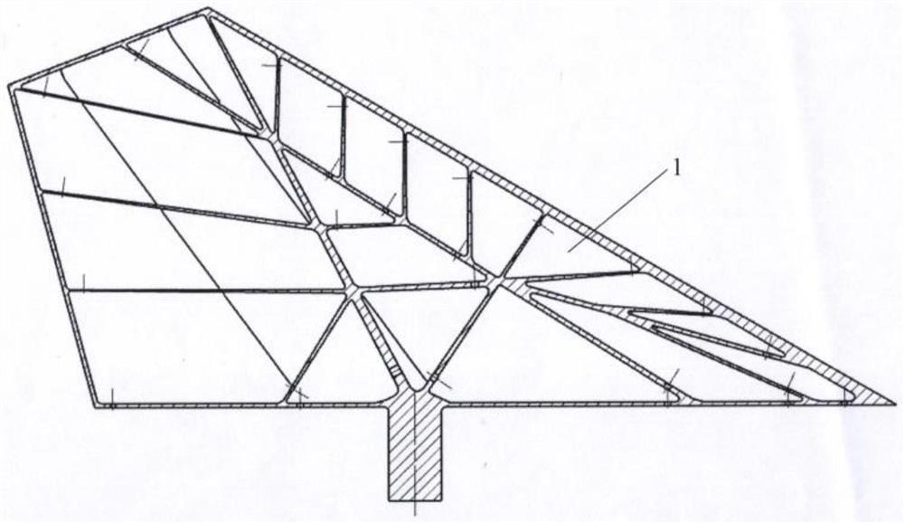
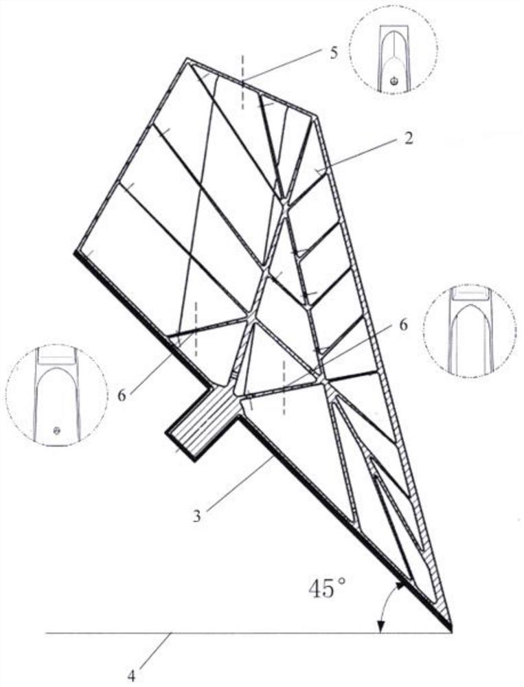
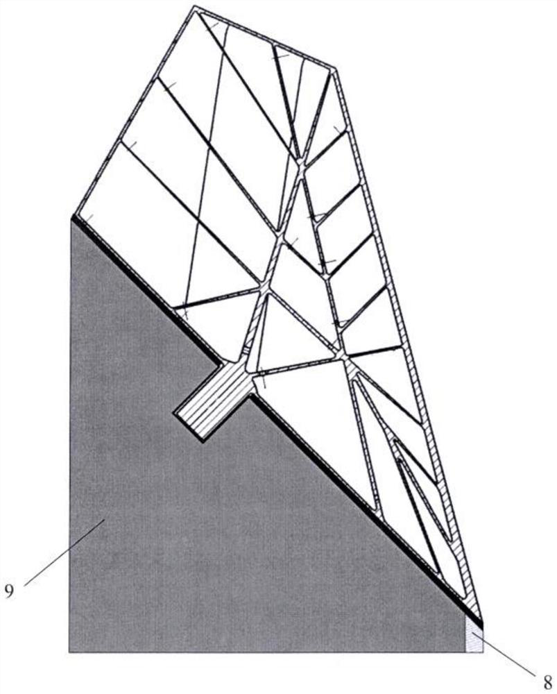
[0031] Using the rudder of a certain type of missile as the carrier, the internal bionic structure design of the rudder is carried out based on the purpose of weight reduction on the basis of satisfying the original strength. Such as Figure 1~3 Shown is a schematic diagram of the bionic structure of the rudder surface. Since the bionic structure of the rudder surface has a thin-walled closed cavity, the design of the laser selective melting forming process is relatively difficult. This embodiment provides a laser selective melting forming process for the bionic structure of the rudder surface. Specific steps are as follows:

[0032] step one:

[0033] The 3D modeling of the rudder surface bionic structure 1 is carried out by using the 3D drawing software UG.

[0034] Add 18 reinforcing ribs according to the bionic structure in the bionic structure 1 of the thin-walled rudder surface; set a powder cleaning hole 2 with a diameter of 2 mm on the edge of the reinforcing rib and...


PUM


Abstract

The invention aims to provide a selective laser melting forming process of a control surface bionic structure. The selective laser melting forming process comprises the specific steps that 1, three-dimensional cartographic software UG is used for modeling of the control surface bionic structure, machining allowance adding and powder clearing hole setting; 2, three-dimensional digital-analog processing software Magics is used for conducting forming and placing, model repairing, support adding and slice filling processing on the control surface bionic structure; 3, the control surface bionic structure is prepared through selective laser melting forming equipment; and 4, after the selective laser melting forming process is completed, powder in an inner cavity is discharged through an inner powder removing hole and an outer powder removing hole, the lower surface grid supporting and solid supporting structure is removed, and the final control surface bionic structure with the same size as the three-dimensional model is obtained. According to the method, the problems of stress concentration, edge cracking, control surface bionic structure deformation, closed control surface bionic structure powder residue and the like in the forming process of the control surface bionic structure or the thin-wall closed inner cavity control surface bionic structure can be solved.

Description

technical field [0001] The invention belongs to the technical field of aero-engine and metal additive manufacturing, and in particular provides a laser selective melting forming process based on a rudder surface bionic structure. Background technique [0002] Laser selective melting technology is a key development process in the field of additive manufacturing technology. With its manufacturing concept completely different from traditional manufacturing technology, it has rapidly developed into a new strategic new direction in the field of front-end manufacturing technology. It is especially suitable for aerospace small-batch rudder surface bionics Efficient and rapid development and customization of structures. However, for the bionic structure of the rudder surface in the aerospace field or the bionic structure of the rudder surface with a thin-walled closed cavity, if the laser selective melting forming technology is used, if the placement is unreasonable, stress concentr...

Claims


Application Information

Patent Timeline
Patent Type & Authority Applications(China)
IPC IPC(8): B22F10/28B22F10/85B22F10/47B33Y10/00B33Y30/00B22F12/00B33Y80/00
CPCB22F10/28B22F10/85B22F10/47B33Y10/00B33Y30/00B22F12/00B33Y80/00Y02P10/25
Inventor 董文启任慧娇王健薛丽媛马慧君
Owner SHENYANG LIMING AERO-ENGINE GROUP CORPORATION
Learn More