Ultrafast laser milling method for fiber composite material

A fiber composite material, ultra-fast laser technology, used in laser welding equipment, welding/welding/cutting items, manufacturing tools, etc., can solve the problems of processing interface burrs, reducing processing accuracy, heat accumulation, etc.

Pending Publication Date: 2022-01-28
BEIJING SATELLITE MFG FACTORY
View PDF0 Cites 1 Cited by
  • Summary
  • Abstract
  • Description
  • Claims
  • Application Information

AI Technical Summary

Problems solved by technology

[0005] On the one hand, the size of the laser knife is in On the order of magnitude, the size of the laser knife is much smaller than the size of the processing structure, resulting in the need to remove materials in multiple layers and multiple passes to form a macro-processing structure. This is also a common problem in almost all laser milling, including traditional lasers; another On the one hand, in the prior art, when ultrafast laser milling is used, the interface of the processing structure, such as the hole wall, and the track filling part, such as the hole area, need to be traversed by the method of cutting the spot or stacking the spot through the same parameters All material parts to be removed
When laser milling is used, since the macroscopic processing structure is generally realized by reciprocating etching of the scanning galvanometer, improper parameters can easily cause heat accumulation, resulting in burrs on the processing interface and reducing processing accuracy

Method used


Image

  • Ultrafast laser milling method for fiber composite material
  • Ultrafast laser milling method for fiber composite material

Examples


Embodiment Construction

[0060] In order to more clearly describe the embodiments of the present invention or the technical solutions in the prior art, the following will briefly introduce the drawings that are used in the embodiments. Apparently, the drawings in the following description are only some embodiments of the present invention, and those skilled in the art can also obtain other drawings according to these drawings without creative efforts.

[0061] The present invention will be described in detail below in conjunction with the accompanying drawings and specific embodiments, and the embodiments cannot be repeated here one by one, but the embodiments of the present invention are not therefore limited to the following embodiments.

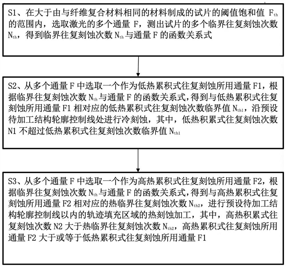
[0062]according to figure 1 Shown, an embodiment of the ultrafast laser milling method for fiber composite material of the present invention, comprises the following steps:

[0063] S1, at a threshold saturation value F greater than the test piece made of the sam...


PUM

PropertyMeasurementUnit
thicknessaaaaaaaaaa

Abstract

The invention relates to an ultrafast laser milling method for a fiber composite material, wherein the material comprises the steps: S1, in a range greater than a threshold saturation value (Fth) of a test piece made of the same material as the fiber composite material, selecting a plurality of fluxes (F) of laser, and measuring a plurality of critical reciprocating etching times (Nth) to obtain a function relational expression between the critical reciprocating etching times (Nth) and the fluxes (F); S2, performing cold etching along a contour control line of a to-be-processed structure, wherein the low-heat accumulation type reciprocating etching times (N1) do not exceed the critical value (Nth1) of the low-heat accumulation type reciprocating etching times; and S3, performing hot etching processing on a track filling area within a preset to-be-processed structure contour control line, wherein the high-heat accumulation type reciprocating etching frequency (N2) is larger than the heat critical reciprocating etching frequency (Nth2). Precise and efficient ultrafast laser milling processing can be achieved, quantitative guidance is provided, the processing effect can be improved, and high repeatability is achieved.

Description

technical field [0001] The invention relates to the technical field of ultrafast laser processing, in particular to an ultrafast laser milling method for fiber composite materials. Background technique [0002] Fiber composite materials represented by inorganic fibers such as carbon fiber and glass fiber, organic fibers such as aramid fiber and PBO, are widely used in aviation due to their physical and chemical properties such as light weight, high strength and high modulus and the advantages of material components that can be designed. Products with force, heat, and electromagnetic functions in military fields such as aerospace and weaponry, and gradually penetrate into civilian fields such as high-end automobiles and rail transit trains. In high-end automobiles, rail transit trains and other fiber composite products, there is a need for local damage repair, and it is necessary to remove a certain depth from the damaged section to the depth of the material; fiber composite ...

Claims


Application Information

Patent Timeline
Patent Type & Authority Applications(China)
IPC IPC(8): B23K26/362B23K26/402B23K26/70B23K103/16
CPCB23K26/362B23K26/402B23K26/70B23K2103/16
Inventor 张加波张开虎路明雨张所来陈钦韬张子岚赵丹妮刘新宇
Owner BEIJING SATELLITE MFG FACTORY
Why Eureka
Try Eureka