[0046] The specific embodiments of the present invention will be described in further detail below with reference to the accompanying drawings and embodiments. The following examples are intended to illustrate the present invention, but not to limit the scope of the present invention.
[0047] Preferred embodiments of the present invention are described in detail as follows in conjunction with the accompanying drawings:
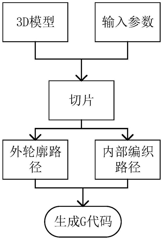
[0048] In this embodiment, the 3D weaving path for the manufacture of molten filaments includes an inner weaving path and an outer contour path, such as Figure 1-3 As shown, the method for generating a 3D weaving path for the manufacture of molten filaments provided by this embodiment includes the following steps:
[0049] (1) Input parameters, the specific operation is to input the surface triangular mesh model (ie 3D model), layer thickness and weaving control parameters to the 3D printing platform, wherein the programming control parameters include weaving path parameters, and the weaving path parameters include filling density, nozzle diameter and number of wires;
[0050] (2) Slicing, using the general uniform slicing method to slice and stratify the input surface triangular mesh model, after that, generate the outer contour path C={c 0 ,c 1 ,...,c i} and axis-aligned bounding box slices B = {b 1 ,b 2 ,...,b i}, each layer c i thickness is h;
[0051] (3) Generate an initial layer l according to the three weaving path parameters of filling density, nozzle diameter and number of wires s and several recurrent layers l j , the loop layer l j It is constructed from multi-layer warp tapes or weft tapes (in this embodiment, the circulation layer has a total of 5 layers, and the path of each layer is 1 (j,k) represents, j represents the cycle layer group number, the value starts from 0, k represents the layer number, k=1, 2, 3, 4, 5), the initial layer l s with the first loop layer l j The first layer path l of (0,1) The filaments cross each other, in the circulation layer l j , the upper and lower adjacent layers l (j,k) with l (j,k+1) filaments cross each other, l (j,5) with l (j+1,1) The filaments cross each other to form an internal braided path with a specific packing density, and finally form a 3D braided structure;
[0052] (4) The outer contour path C and the inner weaving path are alternately generated, and the initial layer l is generated first. s , then in the order {c j*4 , l (j,1) , l (j,2) , c j*4+1 , c j*4+2 , l (j,3) , c j*4+3 , l (j,4) , l (j,5)} Loop, generate the outer contour path and the inner weaving path in turn, until the height of the model is reached. In this way, a 3D weaving path for molten filament fabrication can be obtained.
[0053] (5) Convert 3D weaving path to G-code output.
[0054] Specifically, the inner weaving path consists of an initial layer l s and several recurrent layers l j constitute, as described in step (3), each recurrent layer l j Contains 5 layers of paths, in this embodiment, the initial layer 1 s Generated only in the first layer, recurrent layer l j Repeat until the height of the model to be printed is reached, such as figure 2 shown, its details are:
[0055] In the loop layer l j The weft tapes and warp tapes that are perpendicular to each other will be generated respectively in the center to form an interlocking structure by staggering. Each warp or weft tape is composed of m wires extruded from a nozzle, the thickness of each warp tape or weft tape is h, and the width of each warp tape or weft tape is m×w. The interval between adjacent warp tapes or between adjacent weft tapes is set to m×w, where m is the number of filaments contained in one warp tape or weft tape, and w is the diameter of the nozzle.
[0056] As shown in Fig. 4(a), the starting layer l s The construction process is as follows: generate the weft tape along the y-axis in the Cartesian coordinate system, and calculate the number of weft tapes in this layer according to the width of the axis-aligned bounding box, the width of the weft tape, and the diameter of the nozzle. 1. After generating m filaments, the first weft tape is generated, and then the second weft tape is generated at an interval of m×w, and this cycle is generated until the number of weft tapes reaches t. 1. This layer is printed on a flat surface, and the nozzle does not need to move up and down in the z direction when printing. As shown in Figure 4(b), the initial layer l s There are two heights at different positions, 0 and h.
[0057] As shown in Figure 5(a), l (j,1) The construction process of the layer is: from the starting layer l s The location where the generation starts generates the warp tape along the x-axis. generate to l (j,1) layer and starting layer l s When the overlapped part of the weft tapes is raised, the layer thickness h is raised to continue to generate, and when it reaches the non-overlapping part, it is lowered back to the starting height of the layer to continue to generate. After the first warp band is generated, the next warp band is generated at an interval of m×w, and the number of warp bands t in this layer is calculated according to the length of the axis-aligned bounding box, the width of the warp band and the diameter of the nozzle. 2 , the number of warp tapes reaches the calculated value t 2 , the layer generation ends. As shown in Figure 5(b), l (j,1) Layers have three heights at different locations, 0, h, and 2h.
[0058] As shown in Figure 6(a), l (j,2) The layer construction process is: generate the weft tape along the y-axis. The layer with l (j,1) The warp yarns of the layers are partially overlapped, and when the overlapped part is generated, raise h and continue to generate. In this layer, the interval between the weft tapes is m×w, and the number t of the weft tapes in this layer is calculated according to the length of the axis-aligned bounding box, the width of the warp tape, and the diameter of the nozzle. 3 , the number of weft bands reaches the calculated value t 3 , the layer generation ends. As shown in Figure 6(b), after the generation is completed, l (j,2) Layers have two heights at different locations, h and 2h.
[0059] As shown in Figure 7(a), l (j,3) The construction process of the layer is as follows: the warp tape is generated along the x-axis. This layer is printed on a plane. When printing, the nozzle does not need to move up and down in the z-axis direction. The extrusion volume of this layer is twice that of other layers, that is, this layer The thickness of the warp tape layer is 2h. The interval between the warp tapes is m×w, and the number of warp tapes in this layer is calculated according to the length of the axis-aligned bounding box, the width of the warp tape and the diameter of the nozzle. 4 , the number of warp tapes reaches the calculated value t 4 , the layer generation ends. As shown in Figure 7(b), after the generation is completed, l (j,3) Layers have two heights at different locations, 2h and 3h.
[0060] As shown in Figure 8(a), l (j,4) The construction process of the layer is as follows: the fourth layer is a weft tape generated along the y-axis. When it is generated to the part that does not overlap with the third layer, it needs to drop h and then continue to generate, and when it overlaps, raise h and continue to generate. The number of weft tapes in this layer is equal to l (j,1) The layers are the same, and the space between the weft tapes is m×w. As shown in Figure 8(b), after the generation is completed, l (j,4) Layers have three heights at different locations, 2h, 3h and 4h.
[0061] As shown in Figure 9(a), l (j,5) The construction process of the layers is as follows: the fifth layer is a warp tape generated along the x-axis. When it is generated to the part that does not overlap with the fourth layer, it needs to drop h and then continue to generate, and when it overlaps, raise h and continue to generate. The number of warp tapes in this layer is related to l (j,1) The layers are the same, and the warp bands are spaced m×w apart. As shown in Figure 9(b), after the generation is completed, l (j,5) There are two heights at different locations, 3h and 4h. l (j,5) with l (j+1,1) The layers are interleaved to ensure that the resulting 3D woven structure can be woven in the thickness direction.
[0062]In the step (3), the filling density v=r×d/m×100% of the structure corresponding to the internal weaving path is determined by the actual number of printed wires d in each wire, the theoretical number of printed wires m and the internal control extrusion. The output rate coefficient r is approximated by common interpolation. Among them, r is the magnification of the nozzle extrusion speed e (unit: mm/min). Since the actual number of printed filaments d and the theoretical number of printed threads m both need to be set to positive integers, when printing, in this example, each layer of warp yarn is printed at a constant speed. Tape and weft tape, the extrusion speed e remains constant while v is discrete. For example: when m=5, d=1, 2, 3, 4, 5, the filling density has five discrete values of 20%, 40%, 60%, 80%, and 100%. At this time, it is necessary to change r to make The packing density v varies continuously.
[0063] The specific operation of alternately generating the outer contour path C and the inner weaving path in the step (4) is as follows: first generate l s , then in the order {c j*4 , l (j,1) , l (j,2) , c j*4+1 , c j*4+2 , l (0,3) , c j*4+3 , l (j,4) , l (j,5)} Loop, generate the outer contour path C and the inner path in turn, until the height of the model is reached. For this, the more detailed steps are:
[0064] (4.1) After generating l s After that, the starting layer c of the outer contour is generated 0. At this time, the height of the outer contour is h, and the inner weaving path has two heights at different positions, which are 0 and h respectively;
[0065] (4.2) Generate l of the first loop layer of the inner weaving path (0,1) with l (0,2) , and then generate the first layer c of the outer contour 1 with the second layer c 2. At this time, the height of the outer contour is 3h, and the inner weaving path has two heights at different positions, namely h and 2h;
[0066] (4.3) Generate l of the first loop layer of the inner weaving path (0,3) The third layer c with the outer contour 3. At this time, the height of the outer contour is 4h, and the inner weaving path has two heights at different positions, 2h and 3h respectively;
[0067] (4.4) The l of the first loop layer that finally generates the internal weaving path (0,4) with l (0,5). Once generated, the inner weave path has two heights at different positions, 3h and 4h.
[0068] Repeat steps (4.2) to (4.4) until the model height is reached. Perform a Boolean operation on the outer contour path and the inner weaving path. Here, the operation of the Boolean operation is, for the i-th layer slice, when the path is located in the outer contour path c of the i-th layer of the current layer i Projection b of the bounding box slice B at layer i outside and aligned with the model axis i , the path is not generated. produces results like image 3 As shown, the path represented by the dotted line is the portion not to be generated.
[0069] The descriptions of the above embodiments are only used to help understand the method and the core idea of the present invention. It should be pointed out that for those skilled in the art, without departing from the principle of the present invention, several improvements and modifications can also be made to the present invention, and these improvements and modifications also fall within the protection scope of the claims of the present invention.
[0070] The above description of the disclosed embodiments enables any person skilled in the art to make or use the present invention. Various modifications to these embodiments will be readily apparent to those skilled in the art, and the generic principles defined herein may be implemented in other embodiments without departing from the spirit or scope of the invention. Thus, the present invention is not intended to be limited to the embodiments shown herein, but is to be accorded the widest scope consistent with the principles and novel features disclosed herein.