Supercharge Your Innovation With Domain-Expert AI Agents!

Sand foundation dewatering and drainage method

A foundation and sandy soil technology, applied in the direction of infrastructure engineering, construction, etc., can solve the problems of difficult construction, inapplicability, and difficulty in guaranteeing construction quality, and achieve the effects of ensuring construction quality, long applicable distance, and high construction efficiency

Pending Publication Date: 2022-01-28
SHANGHAI BAOYE GRP CORP
View PDF2 Cites 0 Cited by
  • Summary
  • Abstract
  • Description
  • Claims
  • Application Information

AI Technical Summary

Problems solved by technology

With the continuous maturity of waste incineration power generation technology, waste incineration projects have sprung up in recent years. Due to the strong corrosiveness of domestic waste leachate, it is easy to pollute groundwater sources after leakage. Therefore, the requirements for anti-leakage of garbage ponds are very high. The leachate collection pit at the bottom (pit-in-pit) encounters a sandy foundation, and it is difficult to completely remove the accumulated water in the pit. The construction of the cushion and waterproofing at the bottom of the foundation pit is difficult, and the construction quality is difficult to guarantee
[0003] At present, the methods to solve the dewatering of foundation pits mainly include well point dewatering, pit bottom grouting plugging, gravel blind ditch concealed drainage, etc. Among them, well point dewatering is expensive, and the effect on local sump pits is not obvious; grouting plugging is easy to pollute Groundwater; gravel blind ditch method is not suitable for pit-in-pit far from the edge of the main foundation pit, and gravel blind ditch is easy to block
[0004] In order to solve the above problems, those skilled in the art have proposed the following technical solutions: CN 201811577988.2 discloses a drainage and pressure relief device and a construction method for foundation pits, which use sand-free concrete pipes to lower the groundwater level, and then close the pipes by closing the valves; CN 200910312625.0 discloses a foundation pit dewatering and water saving device and its construction method, which uses sand-free pipes and pebbles backfilled around them as filter layers; although the above means can solve the difficult problem of foundation pit dewatering to a certain extent, it does not The disposal of surface water and rainwater collected in the foundation pit during the construction process was not considered, which put a certain pressure on the drainage performance of the drainage and pressure relief device

Method used


Image

  • Sand foundation dewatering and drainage method
  • Sand foundation dewatering and drainage method
  • Sand foundation dewatering and drainage method

Examples


Embodiment 1

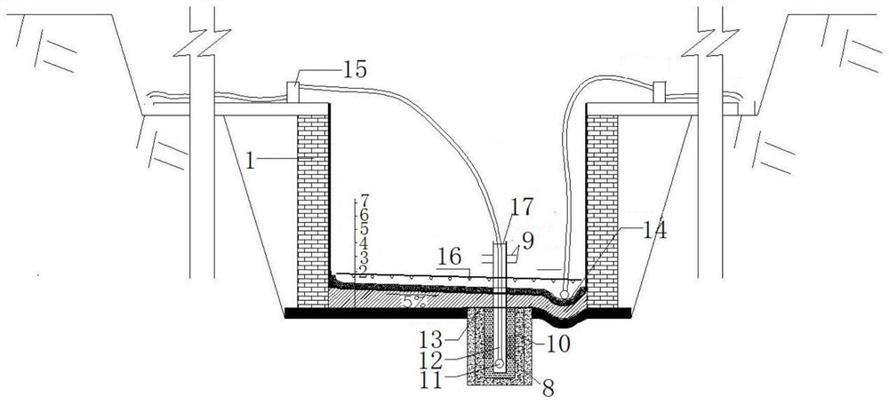
[0043] Substate base residering method, the steps are as follows:

[0044] (1) In the pool bottom of the pit, the bottom of the bottom of the cushion 3 is laid with the second earth wicker 2, and the side wall of the pit is laid. Cave 21 (600mm diameter, depth 800mm);

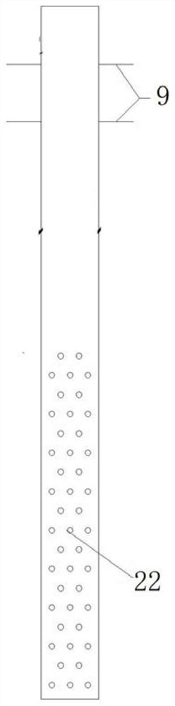
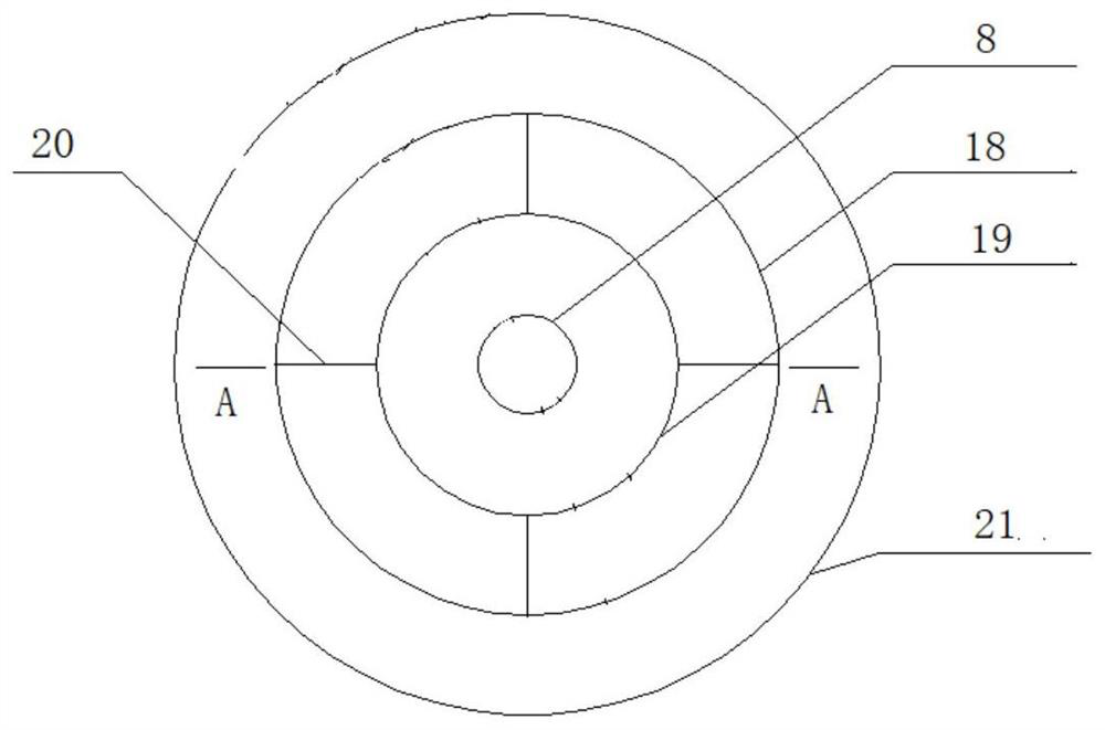
[0045] (2) After the bottom refiner is arranged in the bottom of the pit, arrange it in the pit hole. image 3 and 4 The survey-side refiner layer fabric tool, the peripheral refiner layer fabric manufactured includes a coaxial tooling outer tube 18 and a tool inner tube 19, the inner tube 19 is disposed within the tooling outer tube 18 and the inner tube 19 and the tooling The outer tube 18 is connected by a plurality of positioning reinforcing reinforcing rings perpendicular to the symmetry axis of the tooling outer tube, and the pothole 21 is a gap between the tooling outer tube 18, and the outer tube is perpendicular to the bottom wall of the pit.

[0046] (3) In the housing in the tooling, a vertical arrangemen...


PUM


Abstract

The invention discloses a sand foundation dewatering and drainage method. The method comprises the steps that after a cushion layer is poured at the bottom of a pit-in-pit, a pit hole is formed through downward excavation; a bottom inverted filter layer is arranged at the bottom of the pit hole and then a peripheral inverted filter layer material distribution tool is arranged in the pit hole; a drainage pipe extending out of the pit is vertically arranged in the tool inner pipe, a drainage hole which is horizontally arranged and communicates the interior and the exterior of the drainage pipe is formed in the lower portion of the drainage pipe and located in the pit, and a water stop ring is welded to the upper portion of the drainage pipe; a peripheral inverted filter layer material is uniformly fed; geotechnical cloth is laid on the peripheral inverted filter layer around the drainage pipe along the periphery of the drainage pipe, and a slope making layer and a waterproof roll layer are sequentially laid on the cushion layer and the geotechnical cloth so that a rainwater collecting pit can be reserved in the waterproof roll layer; and a water suction pump is connected to the bottom of the drainage pipe and the rainwater collection pit through guide pipes to pump and drain accumulated water in the pit hole and the rainwater collection pit. According to the method, surface water and rainwater in the foundation pit construction process are comprehensively considered, the construction technology is simple, and the drainage effect is good.

Description

Technical field [0001] The present invention relates to the field of civil construction technology, and it is related to a genus base damping method. Background technique [0002] With the development of scientific and technological development and urbanization, urban domestic garbage increased year by year, and the increasing amount of domestic garbage has brought certain challenges to urban environmental treatment. It is advocated to save energy and achieve sustainable development of resources. Today, waste incineration is not only Urban garbage can be achieved, and the heat generated by incineration waste can be used to power generation, so that the garbage has been used secondary. With the continuous maturity of waste incineration power generation technology, the garbage incineration project is also landed, and the garbage permeation liquid is strong, and the leakage is easy to pollute, so the garbage pool is very high, the garbage pool The bottom leachate is collected (pit p...

Claims


Application Information

Patent Timeline
Patent Type & Authority Applications(China)
IPC IPC(8): E02D19/10
CPCE02D19/10
Inventor 章焰成张静郭小熠孙怀平秦保仁潘新梁
Owner SHANGHAI BAOYE GRP CORP
Features
  • R&D
  • Intellectual Property
  • Life Sciences
  • Materials
  • Tech Scout
  • Unparalleled Data Quality
  • Higher Quality Content
  • 60% Fewer Hallucinations
Learn More