
Infrared detector, camera module and electronic equipment

A technology of infrared detector and infrared light, which is applied in the direction of TV, circuit, color TV, etc., can solve the problems that are not conducive to improving the absorption rate of infrared light, the decrease of the transmittance of the optical window, and the decrease of sensitivity, so as to improve the thermal sensitivity and solve the problem of Cost pain points, the effect of improving absorption rate

Pending Publication Date: 2022-01-28
HUAWEI TECH CO LTD
View PDF0 Cites 1 Cited by
  • Summary
  • Abstract
  • Description
  • Claims
  • Application Information

AI Technical Summary

Problems solved by technology

[0004] In order to reduce the cost of infrared detectors, vTFP packaging (vacuum thin-film packaging, vacuum thin-film packaging) technology is introduced into infrared detectors to replace traditional wafer-level vacuum packaging. The round-level packaging detector saves a wafer packaging process and saves costs, but the transmittance of the optical window is reduced, which is not conducive to improving the absorption rate of infrared light, resulting in the NETD (noise-equivalent temperature difference (noise equivalent temperature difference) is higher than that of traditional detectors, and the sensitivity is lower

Method used

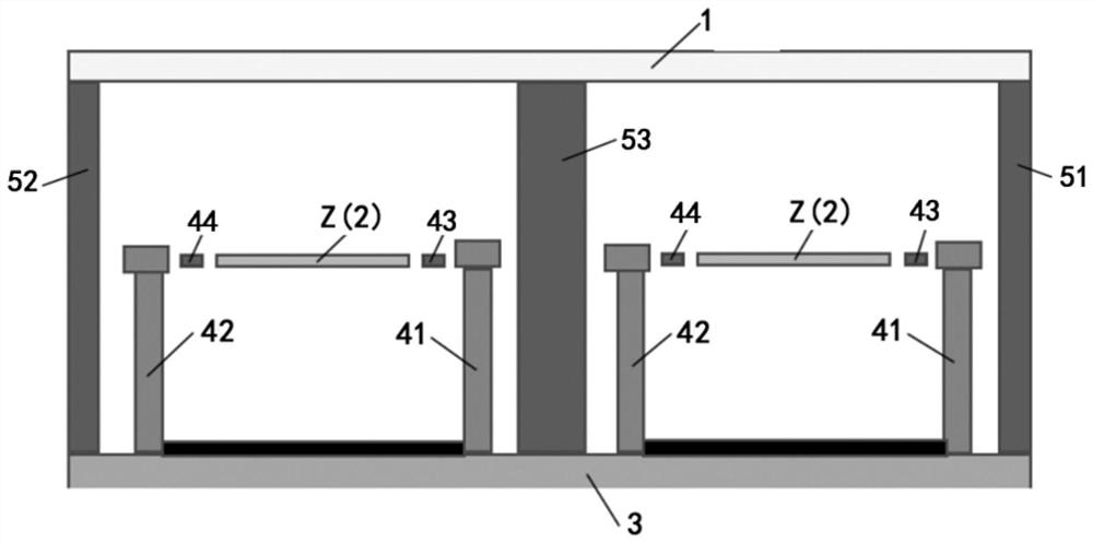
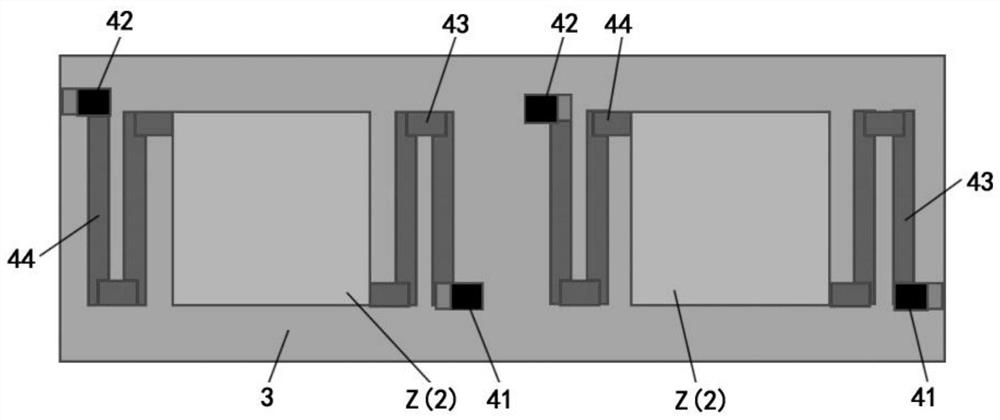
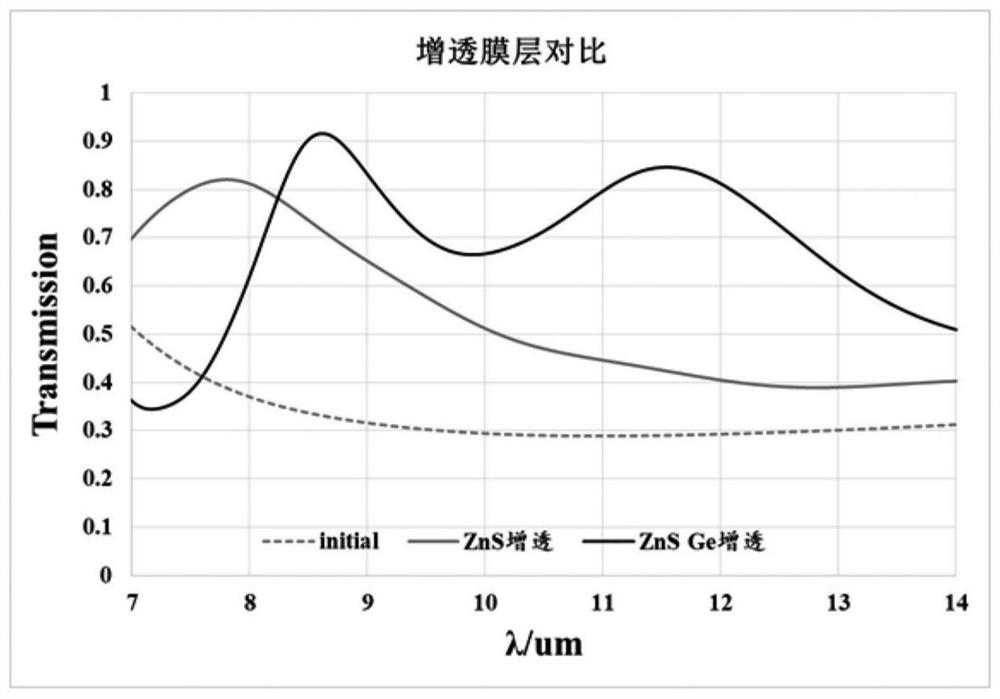

Image

  • Infrared detector, camera module and electronic equipment
  • Infrared detector, camera module and electronic equipment
  • Infrared detector, camera module and electronic equipment

Examples


Embodiment Construction

[0049] The technical solutions in the embodiments of the present application will be described below with reference to the drawings in the embodiments of the present application.

[0050] In the description of this application, the terms "center", "upper", "lower", "front", "rear", "left", "right", "vertical", "horizontal", "top", " The orientation or positional relationship indicated by "bottom", "inner", "outer", etc. is based on the orientation or positional relationship shown in the drawings, and is only for the convenience of describing the application and simplifying the description, rather than indicating or implying the referred device or Elements must have certain orientations, be constructed and operate in certain orientations, and thus should not be construed as limiting the application.

[0051] In the description of this application, it should be noted that unless otherwise specified and limited, the terms "installation", "connection" and "connection" should be un...


PUM


Abstract

The embodiment of the invention provides an infrared detector, a camera module and electronic equipment. The infrared detector comprises an optical window, a thin film layer, a reflecting layer and a reading circuit layer which are stacked in sequence; the thin film layer comprises an absorption layer and a conversion layer, and the absorption layer is located between the optical window and the conversion layer; the optical window is used for incidence of infrared light, the absorption layer is used for absorbing the infrared light and converting the infrared light into heat energy, and the conversion layer is used for converting the heat energy into electric signals; the reflecting layer is used for reflecting the infrared light so as to increase the infrared light absorbed by the absorbing layer; the reading circuit is used for processing the electric signal, and the processed electric signal is used for forming a thermal infrared image; and the infrared detector further comprises a metasurface layer arranged on at least one of the optical window and the thin film layer, the metasurface layer comprises a plurality of microstructures arranged periodically, and the metasurface layer can improve the absorptivity of the absorption layer. According to the embodiment of the invention, the absorption rate of infrared light is improved, the noise equivalent temperature difference is reduced, and the sensitivity is improved.

Description

technical field [0001] The present application relates to the field of infrared detection equipment, in particular to an infrared detector, a camera module and electronic equipment. Background technique [0002] A thermal imaging camera, also commonly referred to as an infrared camera, is a camera that displays images by receiving infrared rays emitted by objects. Any object with temperature will emit infrared rays. The infrared thermal imager is to receive the infrared rays emitted by the object, display the temperature distribution on the surface of the measured object through colored pictures, and find out the abnormal points of temperature according to the small difference in temperature. to the role of maintenance. [0003] Infrared thermal imaging cameras are generally composed of four parts: detectors, signal processors, displays, and optical systems. The core component is the infrared detector. The infrared thermal imaging camera uses the infrared detector and the ...

Claims


Application Information

Patent Timeline
IPC IPC(8): H01L27/146H01L31/0232H01L31/0236H01L31/09H04N5/33
CPCH01L27/14669H01L27/14625H01L27/14629H01L27/14618H01L31/0236H01L31/0232H01L31/09H04N5/33
Inventor 邹正鹏克里斯特尔·洛伊克·蒂塞代郁峰
Owner HUAWEI TECH CO LTD
Learn More