A kind of chemical condenser and method for using it to condense and separate gas phase products

A condensation separation and condenser technology, applied in separation methods, chemical instruments and methods, vapor condensation, etc., can solve problems such as reducing heat transfer coefficient, affecting condensation effect, affecting reaction effect, etc., to reduce solubility, improve condensation efficiency, The effect of reducing the condensing load

Active Publication Date: 2022-05-06
DONGYING HI TECH SPRING CHEM IND +1
View PDF7 Cites 0 Cited by
  • Summary
  • Abstract
  • Description
  • Claims
  • Application Information

AI Technical Summary

Problems solved by technology

Using these condensers, although the high-boiling point substances can be condensed into liquids, the uncondensed ammonia and CO cannot be condensed in time. 2 Separated from the condensate, the gas and liquid form a gas-liquid mixture inside, thereby reducing the heat transfer coefficient and affecting the condensation effect
It is even more unable to dissolve or entrain ammonia and CO in the condensate 2 Separate as much as possible, so that the condensate that dissolves or entrains a large amount of ammonia is returned to the reactor, which affects the reaction effect

Method used


Image

  • A kind of chemical condenser and method for using it to condense and separate gas phase products
  • A kind of chemical condenser and method for using it to condense and separate gas phase products
  • A kind of chemical condenser and method for using it to condense and separate gas phase products

Examples


Embodiment 1

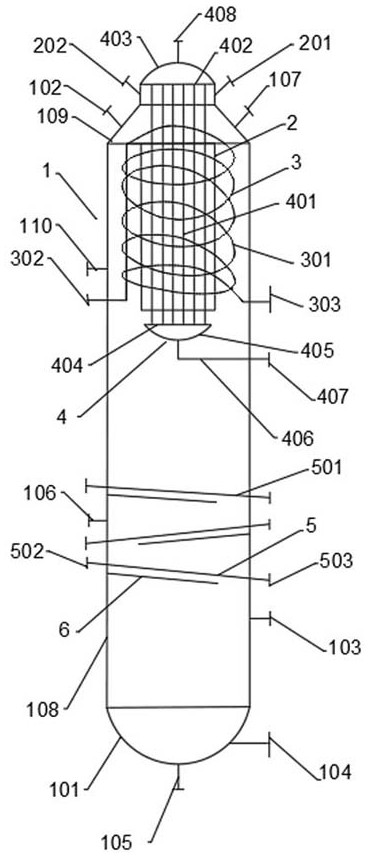
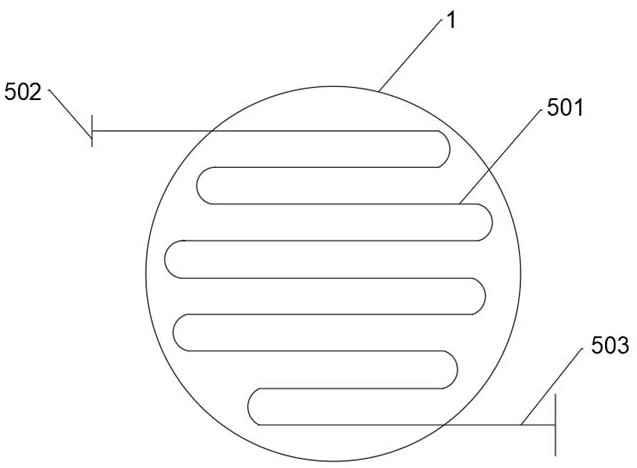
[0035] Such as Figure 1-5 As shown, the embodiment of the present invention provides a chemical condenser, including an outer cylinder 1, an inner isolation cylinder 2, a coil condenser 3, an exposed tube condenser 4, a coil heater 5 and a film-forming plate 6; the outer cylinder 1. It consists of an outer cylinder body 108, an outer cylinder upper head 109 and an outer cylinder lower head 101. The upper part of the outer cylinder body 108 is a condensation area, and the lower part is a separation area; the inner isolation cylinder 2 runs through the upper part of the outer cylinder 1 Extending to the inside of the outer cylinder 1 and connected to the upper head 109 of the outer cylinder, the outer side of the inner isolation cylinder 2 is the primary cooling zone, and the inside is the deep cooling zone; the coil condenser 3 is located inside the primary cooling zone and is composed of condensing coils 301 The bare tube condenser 4 is made up of the condensing tube 401, the...

Embodiment 2

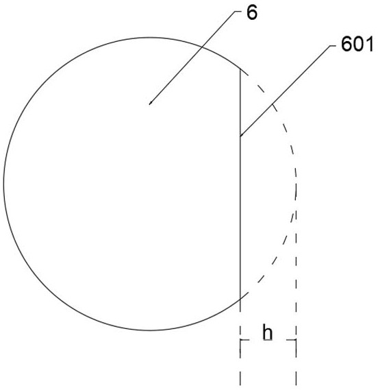
[0051] The condensing separator of this embodiment is the same as that of Embodiment 1. The difference between this embodiment and Embodiment 1 is that: the coil heater 5 is closely attached to the top of the film-forming plate 6 and is located 600 mm below the bottom head 405 of the condensation tube. , the angle between the coil heater 5 and the outer cylinder 108 is equal to the angle α between the film-forming plate 6 and the outer cylinder 108, and the angle α is 92°. Three coil heaters, 3 film-forming plates, the film-forming plate 6 is a circular plate with a diameter equal to the diameter of the outer cylinder body 108, and a part of the inferior circle is cut off, and the maximum linear distance h between the cut-off inferior circle arc and the chord is the cylinder body 4 / 15 of the diameter; the minimum distance g between two adjacent film-forming plates 6 is equal to h, and the upper interface 103 of the liquid level gauge is located at 600 mm below the film-forming ...

Embodiment 3

[0055] The condensing separator of this embodiment is the same as that of Embodiment 1, and the difference from Embodiment 1 is that: the coil heater 5 is closely attached to the top of the film-forming plate 6, and is located at 1000mmc below the lower head 405 of the condensing tube, and the film-forming plate The included angle α between 6 and the outer cylinder body 108 is 95°, 5 coil heaters, 5 film-forming plates, and the maximum linear distance h between the inferior circle cut off by the film-forming plate 6 and the chord is 1 / 3 of the cylinder diameter; the minimum distance g between two adjacent film-forming plates 6 is equal to h; the upper interface 103 of the liquid level gauge is located at 1000 mm below the film-forming plates 6 .

[0056] The method of using the above-mentioned condensing separator to condense and separate urea and ethylene glycol to react to prepare a gas mixture with a discharge temperature of 140°C from the ethylene carbonate reactor is the s...


PUM


Abstract

The invention provides a chemical condenser and a method for condensing and separating gas phase products using it, and relates to the field of chemical condensers. The chemical condenser includes an outer cylinder, an inner isolation cylinder, a coil condenser, an exposed tube condenser, and a coil A heater and a film-forming plate; the outer cylinder is composed of an outer cylinder body, an outer cylinder upper head and an outer cylinder lower head, the upper part of the outer cylinder body is a condensation area, and the lower part is a separation area. The present invention utilizes part of the urea and ethylene glycol reaction to prepare the mixed gas discharged from the ethylene carbonate reactor as the heat source of the coil heater, which avoids the use of additional heating medium and plays an energy-saving role; Part of the high-boiling point substances in the gas condense and liquefy, and make them leave the initial cooling zone in time and fall into the heating zone, so that the high-boiling point substances in the mixed gas entering the cryogenic zone are reduced, reducing the condensation load in the cryogenic zone , which improves the condensation efficiency in the cryogenic zone.

Description

technical field [0001] The invention relates to the technical field of chemical condensers, in particular to a chemical condenser and a method for using it to condense and separate gas phase products. Background technique [0002] The reaction of urea and ethylene glycol to prepare ethylene carbonate is generally carried out at -0.01~-0.09MPa, 140~170°C, and a hydroxyl group of urea and ethylene glycol first reacts to form the intermediate hydroxyethyl carbamate methyl ester And release a molecule of ammonia, the intermediate hydroxyethyl carbamate methyl ester is then cyclized to generate ethylene carbonate and release another molecule of ammonia. The reaction is a reversible equilibrium reaction. The presence of ammonia can inhibit the reaction, so it needs to be released in time The ammonia gas produced by the reaction, on the other hand, because the raw material urea and ethylene glycol contain a small amount of water, these water can react with urea preferentially to ge...

Claims


Application Information

Patent Timeline
Patent Type & Authority Patents(China)
IPC IPC(8): B01D5/00
CPCB01D5/0036B01D5/0039
Inventor 肖福魁张生安滕文彬曹德龙杨金海
Owner DONGYING HI TECH SPRING CHEM IND
Why Eureka
Try Eureka