Diffuse reflection coating and diffuse reflection coating layer
A diffuse reflection and coating technology, which is applied in the field of diffuse reflection coating and diffuse reflection coating, can solve the problems of high raw material cost and low reflectivity of diffuse reflection coating, achieve excellent reflectivity, reduce raw material cost, and broaden the application field Effect
- Summary
- Abstract
- Description
- Claims
- Application Information
AI Technical Summary
Problems solved by technology
Method used
Image


Examples
Embodiment 1
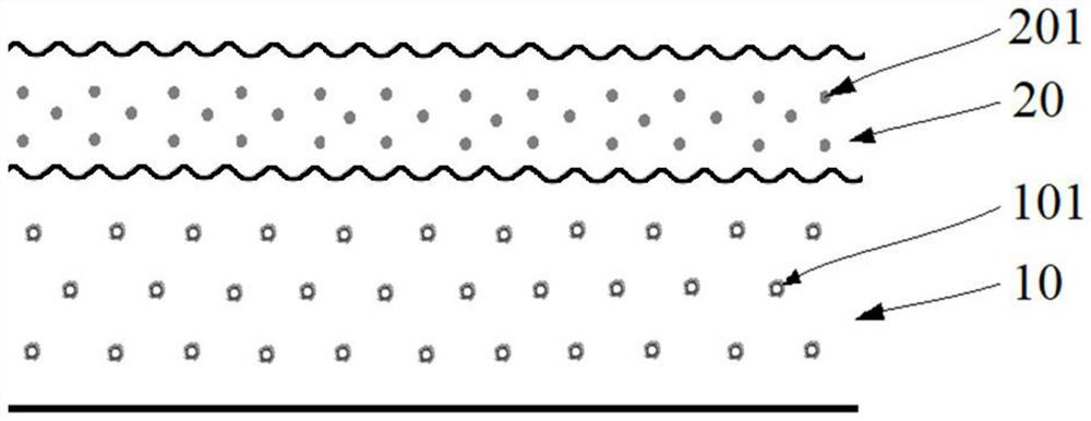
[0072] The diffuse reflective paint in Example 1 includes a first paint and a second paint used in conjunction with the first paint.
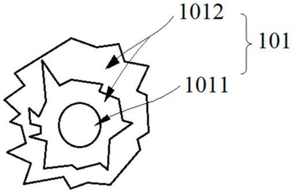
[0073] Wherein, the first coating includes the first resin: 100 parts by weight of acrylic resin, 100 parts by weight of the first filler 101, coalescent: 4.2 parts by weight of propylene glycol butyl ether, dispersant: 3.1 parts by weight of polyacrylate, Thickener: 3.5 parts by weight of hydroxyethyl cellulose ether, defoamer: 1.2 parts by weight of silicone defoamer; wherein, the shape of the first filler 101 is burr-like, and the core 1011 of the first filler 101 The material is rutile titanium dioxide, the particle size of the core 1011 is 0.4 μm-0.6 μm, the material of the shell layer 1012 is alumina, and has a double-layer structure, and the average thickness is 0.1 μm-0.2 μm. The refractive index of the first filler 101 is index of 2.7, the refractive index of the first resin is 1.5, the absolute value of the difference between the refr...
Embodiment 2
[0077] Embodiment 2 Referring to the embodiment of Embodiment 1, the difference is that the material of the core 1011 of the first filler 101 is anatase titanium dioxide, the refractive index of the first filler 101 is 2.6, and the refractive index of the first resin is the same as that of the first resin. The absolute value of the difference in refractive index of the first filler 101 is 1.1, and the reflectance of the first filler 101 in the 0.4 μm-2.5 μm wave band is 92%.
Embodiment 3
[0079] Example 3 Referring to the implementation of Example 1, the difference is that the material of the shell layer 1012 of the first filler 101 is silicon oxide, the refractive index of the first filler 101 is 2.5, and the refractive index of the first resin is the same as that of the first filler. The absolute value of the difference in the refractive index of 101 is 1.0, and the reflectance of the first filler 101 in the 0.4 μm-2.5 μm wave band is 93%.
PUM
| Property | Measurement | Unit |
|---|---|---|
| Particle size | aaaaa | aaaaa |
| The average thickness | aaaaa | aaaaa |
| Thickness | aaaaa | aaaaa |
Abstract
Description
Claims
Application Information
 - R&D
- Intellectual Property
- Life Sciences
- Materials
- Tech Scout
- Unparalleled Data Quality
- Higher Quality Content
- 60% Fewer Hallucinations
Browse by: Latest US Patents, China's latest patents, Technical Efficacy Thesaurus, Application Domain, Technology Topic, Popular Technical Reports.
© 2025 PatSnap. All rights reserved.Legal|Privacy policy|Modern Slavery Act Transparency Statement|Sitemap|About US| Contact US: help@patsnap.com