
Built-in perforated steel plate composite shear wall

A technology of combining shear walls and perforated steel plates, which is applied to walls, building materials, building components, etc., can solve the problems of complex construction of combined shear walls, loss of concrete slabs on both sides, and low efficiency of cooperative stress, and achieve enhanced Collaborative work ability, avoid local buckling and steel plate tearing, solve the effect of cumbersome pouring process

Pending Publication Date: 2022-02-01
SUZHOU UNIV OF SCI & TECH
View PDF3 Cites 2 Cited by
  • Summary
  • Abstract
  • Description
  • Claims
  • Application Information

AI Technical Summary

Problems solved by technology

The traditional combined shear wall is a thin steel plate with studs welded inside, and the studs are used as shear connectors to connect with the reinforced concrete slabs on both sides. In addition to the residual stress and initial defects, there is still the problem of steel plate failure and tearing; on the other hand, once the concrete is crushed and peeled off, the connection between the reinforced concrete slab and the studs will be destroyed, and the later buckling restraint of the concrete slabs on both sides will be lost. Moreover, when the force is applied, the tensile field of some steel plates with or without openings is not orthogonal to the pressure field of the concrete slab, and the efficiency of coordinative force bearing is low. At the same time, the construction of such combined shear walls is also relatively cumbersome. Reinforced concrete slabs need to be poured in batches on both sides, which will also cause the problem of asymmetric center of gravity

Method used


Image

  • Built-in perforated steel plate composite shear wall
  • Built-in perforated steel plate composite shear wall
  • Built-in perforated steel plate composite shear wall

Examples


Embodiment Construction

[0020] The invention will be described in detail below with reference to the accompanying drawings.

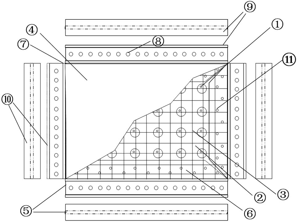
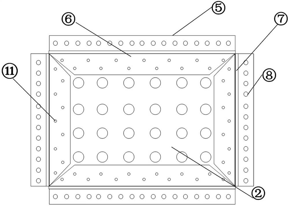
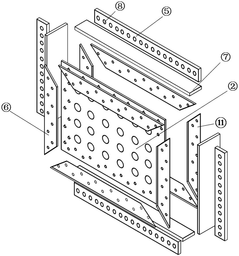
[0021] like Figure 1 to 3 As shown, a built-in open-hole steel plate combination shear wall includes a hole steel plate 2, and the end plate 7 is provided with an end plate 7, located in the inner side of the end plate 7 and in the opening. The steel sheet 2 is provided with a splicing plate 6, and the splicing plate 6 is bolted with the openings 2, and the splicing plate 6 is welded to the end plate 7 by longitudinal weld.

[0022] like figure 1 , Figure 4 to 6 Design, a steel mesh 3 is provided on both sides of the plate surface of the open hole steel plate 2, and there are several openings on the plate surface of the opening plate 2 by the splicing plate 6, and in the opening In connection with the pulling bib 1, both ends of the pulling thus 1 are connected to the steel mesh 3 on both sides, the pulling bib 1, the open steel plate 2 and the steel sheet form a structural skelet...


PUM


Abstract

The invention relates to a built-in perforated steel plate composite shear wall, which comprises a perforated steel plate, reinforcing meshes are arranged on two sides of the plate surface of the perforated steel plate, a plurality of holes are uniformly distributed in the plate surface of the perforated steel plate, tie bars are connected in the holes in a penetrating manner, two ends of each tie bar are respectively connected with the reinforcing meshes on two sides, the tie bars, the perforated steel plates and the reinforcing meshes form a structural framework, and the structural framework is subjected to one-time pouring in a cast-in-place concrete mode till the two sides are filled to form concrete slabs. The distribution of a tension field is adjusted mainly through the perforated steel plates, the cooperative work capacity of the steel plate tension field and a concrete plate pressure field is enhanced, the lateral stiffness, energy dissipation capacity and ductility of the combined shear wall are greatly improved, meanwhile, the defect that the pouring process of a traditional stud combined shear wall is tedious is overcome, the construction efficiency is improved, the structure is simple, cost is low, and construction is convenient and efficient, performance is remarkably improved, and the built-in perforated steel plate composite shear wall is suitable for lateral resistance and energy consumption improvement of engineering structures.

Description

Technical field [0001] The present invention relates to the field of civil engineering combined structures, and in particular, there is a built-in steel sheet combination shear wall. Background technique [0002] With the improvement of the development and construction technology of the state, my country's high-rise buildings are steadily advanced in terms of high height and superior power performance. Also accompanying the height of the building, the structure is getting higher in response under lateral effects of earthquake, wind, and even the collapse of the anti-side capacity or the lack of energy consumption, seriously affects the use and operation safety of high-rise buildings. . my country is also an earthquake, Taiwan (hurricane), has a natural disaster, effectively enhancing the anti-side capacity of high-rise buildings is the technical problem to be solved. [0003] In recent years, domestic and foreign scholars have promoted the extensive research from all kinds of she...

Claims


Application Information

Patent Timeline
IPC IPC(8): E04B2/84E04C2/08E04C2/30E04C2/38
CPCE04B2/842E04C2/08E04C2/30E04C2/384
Inventor 夏志远方有珍陈赟郭彤唐柏鉴史慧媛
Owner SUZHOU UNIV OF SCI & TECH
Learn More