Voltage conversion circuit and charging equipment

A technology of voltage conversion circuit and branch circuit

Active Publication Date: 2022-02-01
HALO MICROELECTRONICS CO LTD
View PDF8 Cites 6 Cited by
  • Summary
  • Abstract
  • Description
  • Claims
  • Application Information

AI Technical Summary

Problems solved by technology

[0004] However, in this circuit, the output voltage of the rectification unit (that is, the voltage of the first voltage terminal Vrect) is filtered by the capacitor Crect, and the wireless charging input that originally has the characteristics of a current source is converted into a voltage source, which also makes the step-down unit The flying capacitors (such as capacitors C101 and capacitors C102) will generate current spikes during the charging process, which will affect the voltage conversion efficiency

Method used


Image

  • Voltage conversion circuit and charging equipment
  • Voltage conversion circuit and charging equipment
  • Voltage conversion circuit and charging equipment

Examples


Embodiment Construction

[0131] In order to make the purposes, technical solutions and advantages of the embodiments of the present application clearer, the technical solutions in the embodiments of the present application will be clearly and completely described below in conjunction with the drawings in the embodiments of the present application. Obviously, the described embodiments It is a part of the embodiments of this application, not all of them. Based on the embodiments in this application, all other embodiments obtained by persons of ordinary skill in the art without creative efforts fall within the protection scope of this application.

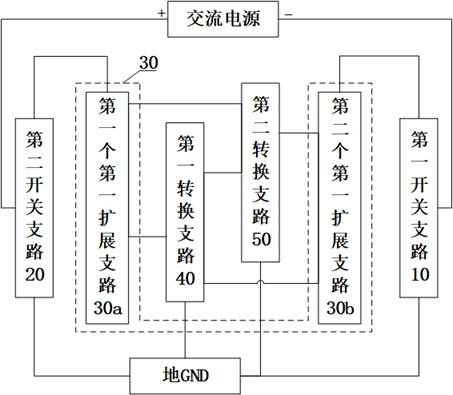
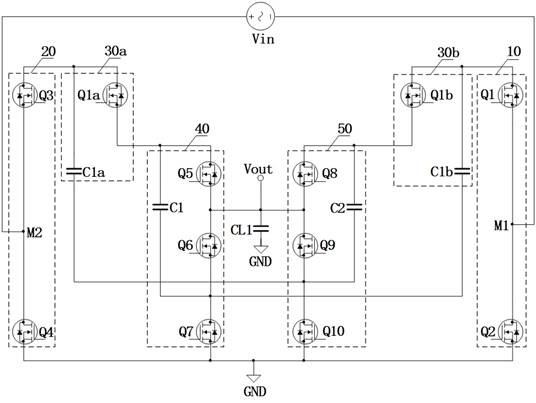
[0132] Please refer to figure 2 , figure 2 A schematic structural diagram of a voltage conversion circuit provided in an embodiment of the present application. Such as figure 2 As shown, the voltage conversion circuit includes a first switch branch 10, a second switch branch 20, a first conversion branch 40, a second conversion branch 50, 2N first exten...


PUM


Abstract

The invention discloses a voltage conversion circuit and charging equipment, and relates to the technical field of electronic circuits. The voltage conversion circuit comprises a primary switch branch, a secondary switch branch, a primary conversion branch, a secondary conversion branch, 2N primary expansion branches and a control unit, wherein the 2N first expansion branches comprise a first primary expansion branch and a second primary expansion branch; the primary switch branch is connected with the second primary expansion branch and an alternating-current power supply; the secondary conversion branch is connected with the primary conversion branch, the first primary expansion branch and the second primary expansion branch; the primary conversion branch is connected with the first primary expansion branch and the second primary expansion branch; the secondary switch branch is connected with the alternating-current power supply and the first primary expansion branch; and the control unit is used for controlling on or off of switches in the primary switch branch, the secondary switch branch, the primary conversion branch, the secondary conversion branch and the primary expansion branches. In this way, voltage conversion efficiency can be improved.

Description

technical field [0001] The present application relates to the technical field of electronic circuits, in particular to a voltage conversion circuit and a charging device. Background technique [0002] Currently, using wireless charging to power batteries is becoming more and more popular in smartphones. Since the energy transmitted by the wireless charging transmitter is transmitted in the form of a magnetic field, a wireless charging receiver must be used to convert the magnetic field energy into electrical energy. In order to achieve high efficiency, the coil operating voltage of the wireless charging receiver needs to be set higher to reduce the power consumption of the resistor in the receiver coil. In this case, then, for a single-cell battery-powered system, two charge-pump-based converters need to be cascaded to reduce the output voltage of the wireless charging receiver to a voltage that can be used to power a single cell. [0003] In practical applications, it is ...

Claims


Application Information

Patent Timeline
Patent Type & Authority Applications(China)
IPC IPC(8): H02M7/217H02M3/158H02M1/088H02J7/02
CPCH02M7/217H02M3/158H02M1/088H02J7/02H02J2207/20
Inventor 韩双杨松楠刘锐
Owner HALO MICROELECTRONICS CO LTD
Why Eureka
Try Eureka