
Plate grooving machine

A slotting machine and plate technology, which is applied to metal processing machinery parts, metal sawing equipment, driving devices, etc., can solve the problems of difficulty in adjusting the correct inclination angle of the driven wheel, large groove depth error, and frequent replacement of the driven wheel, etc. Easy maintenance and replacement, long service life and good processing quality

Pending Publication Date: 2022-02-08
赵俊儒
View PDF1 Cites 0 Cited by
  • Summary
  • Abstract
  • Description
  • Claims
  • Application Information

AI Technical Summary

Problems solved by technology

[0003] In order to solve the defects in the background technology that the driven wheel is frequently replaced due to wear and tear, and it is difficult to restore the original correct inclination angle during replacement. The invention provides a plate slotting machine, which not only solves the problems of frequent replacement of driven wheels and difficulty in adjusting the correct inclination angle of driven wheels, but also overcomes the defect of large groove depth errors caused by upper slotting

Method used


Image

  • Plate grooving machine
  • Plate grooving machine
  • Plate grooving machine

Examples


Embodiment 1

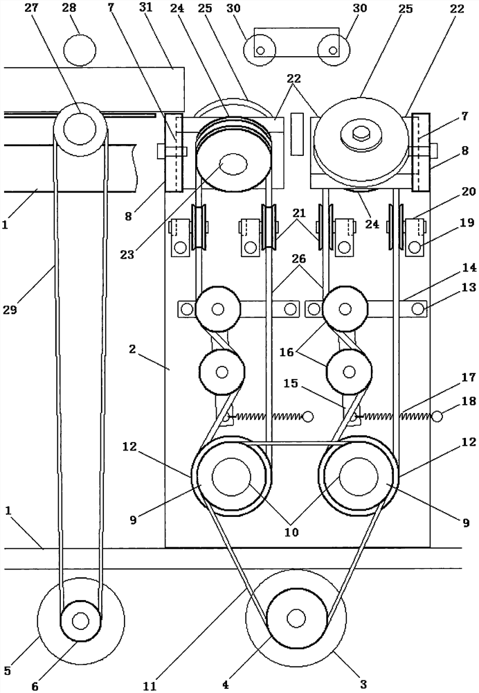
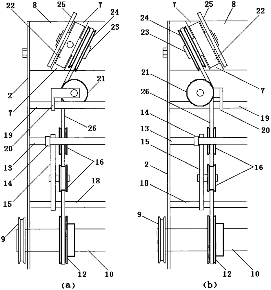
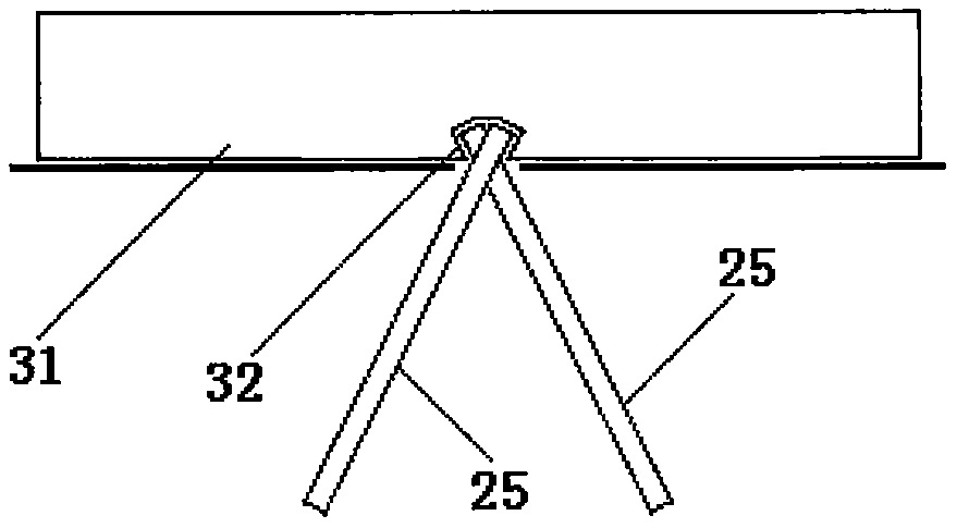
[0026] Example 1: Combining figure 1 , figure 2 , during slotting, the slotting motor 3 and the plate-feeding motor 5 start, and drive the driving wheel 9 of the front and rear two sets of slotting devices and the lower sheave 12 on the driving wheel 9 to rotate coaxially through the toothed belt 11, and the lower groove The wheel 12 drives the upper sheave 24 and the circular saw blade 25 to rotate coaxially through the transmission belt 26. At the same time, the tension springs 17 of the front and rear two sets of slotting devices have been pulling the movable wheel frame 15 to keep the tension wheel 16 in an elastic tension state. , so that the drive belt 26 will not slip due to slack and lose rotation, and the reversing wheels 21 of the front and rear slotting devices keep the upper sheave 24 and the circular saw blade 25 in the normal rotation in the inclined state; then put the plate 31 and the grooving face is sent to the grooving station by the lower roller 27 and th...

Embodiment 2

[0027] Embodiment 2: the processing of plates 31 with different groove depths can be realized by adjusting the circular saw blades 25 of different diameters; height; because the present invention adopts the lower slotting scheme and replaces the ordinary circular saw blade with a milling cutter, it can also ensure consistent groove depth and smooth edges when processing plates with obvious thickness errors.

Embodiment 3

[0028] Embodiment 3: The number of slotting units is correspondingly increased or decreased according to the number of slots on each plate 31; when it is necessary to slot on both sides of the plate 31, the slots on both sides should be staggered to avoid opening on the same parallel line.


PUM


Abstract

The invention discloses a plate grooving machine which comprises a machine frame, wall plates fixed to the two sides of the machine frame, a grooving motor arranged below the machine frame, a plate walking motor, a cross beam arranged between the wall plates on the two sides and provided with an inclined groove and a plurality of grooving units, each grooving unit comprises a front grooving device and a rear grooving device, each set of grooving device comprises a driving wheel, a main shaft, a tooth-shaped belt, a lower grooved wheel, a large bracket shaft, a large bracket, a movable wheel frame, a tensioning wheel, a tension spring, a tension spring shaft, two small bracket shafts, two small brackets, two reversing wheels, a wheel seat, a wheel seat shaft, an upper grooved wheel, a circular saw blade, a transmission belt, a lower roller and an upper roller which are arranged on the machine frame, and a press wheel arranged above the circular saw blade. According to the invention, one or more parallel or transversely and vertically crossed grooves which are small in outside and wide in inside can be machined in one face or two faces of plates made of different materials, long-time stable and reliable work can be achieved, the service life is long, the failure rate is low, maintenance and replacement are easy, and the machining quality is good.

Description

technical field [0001] The invention relates to a grooving machine, in particular to a grooving machine for a slab that processes grooves that are small on the outside and wide on the inside. Background technique [0002] The boards used for veneer, especially the external wall insulation boards, must be brushed or designed with concave-convex lines on the pasting surface to increase the attachment area, make the paste firm and not fall off, and avoid deformation and warping, but the actual application effect is not good. It is not ideal. For example, it is not uncommon for the fireproof board used to wrap the outer wall of the building to deform and fall off due to degumming. This not only affects the construction quality, but also directly endangers personal and property safety due to the falling of the high-level board. In order to solve this problem, the Chinese patent announcement number CN104209975 A, the announcement date of December 17, 2014, discloses a kind of "pla...

Claims


Application Information

Patent Timeline
Patent Type & Authority Applications(China)
IPC IPC(8): B23D45/10B23D47/12B23D47/04B23C3/28B23Q5/10B23Q7/00B26D3/06B26D7/06
CPCB23D45/10B23D47/12B23D47/042B23C3/28B23Q5/10B23Q7/00B26D3/065B26D7/06
Inventor 赵俊儒
Owner 赵俊儒
Learn More