
Concrete pouring method for large steel ladle reinforced concrete protective door

A reinforced concrete and protective door technology, which is applied in the direction of buildings, door leaves, windows/doors, etc., can solve the problems affecting the appearance quality of steel-laden reinforced concrete protective doors, affecting the overall force of steel-laden reinforced concrete protective doors, and the combination of steel plates and concrete is not compact, etc. problems, to achieve the effect of strengthening the construction quality of filling, avoiding dryness and cold joints, and reducing the difficulty of construction

Active Publication Date: 2022-02-08
SINOHYDRO BUREAU 7 CO LTD
View PDF10 Cites 0 Cited by
  • Summary
  • Abstract
  • Description
  • Claims
  • Application Information

AI Technical Summary

Problems solved by technology

The biggest disadvantages of this method are: 1. The door panel is not easy to level when it is laid flat, and a cavity interlayer is easily formed between the concrete surface and the steel door panel at the end of the concrete pouring stage, resulting in the incomplete combination of the steel plate and the concrete, which ultimately affects the ladle reinforced concrete. The overall force of the protective door; 2. Due to the large slump of the pumped concrete, which generally reaches 160mm-200mm, if the protective door is not placed horizontally during the horizontal concrete pouring, it is easy to cause local deformation of the steel door panel, thereby Affect the overall appearance quality of the ladle reinforced concrete protective door, and at the same time cause hidden dangers to the opening and closing operation of the subsequent protective door

Method used


Image

  • Concrete pouring method for large steel ladle reinforced concrete protective door
  • Concrete pouring method for large steel ladle reinforced concrete protective door
  • Concrete pouring method for large steel ladle reinforced concrete protective door

Examples


Embodiment Construction

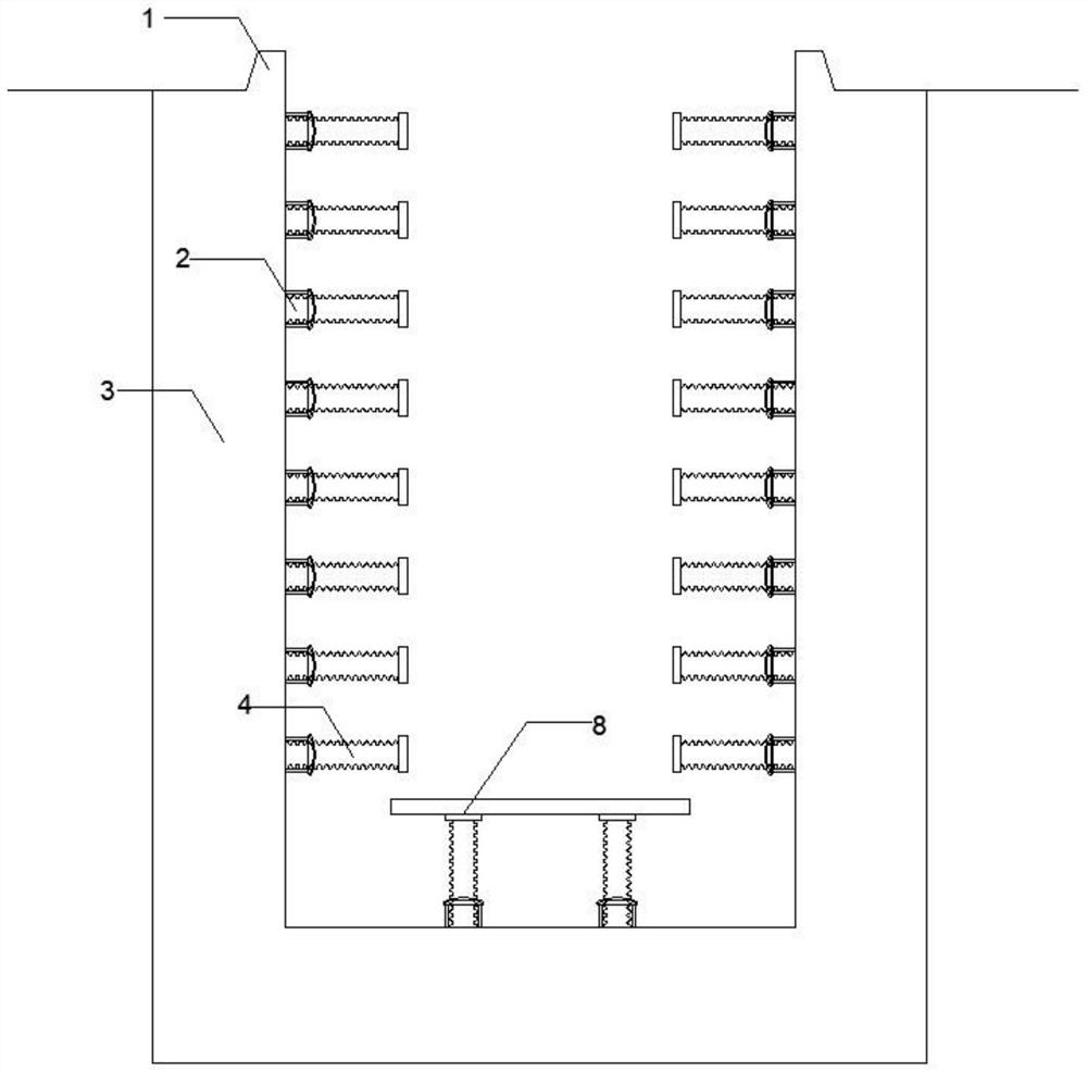
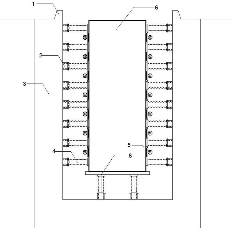
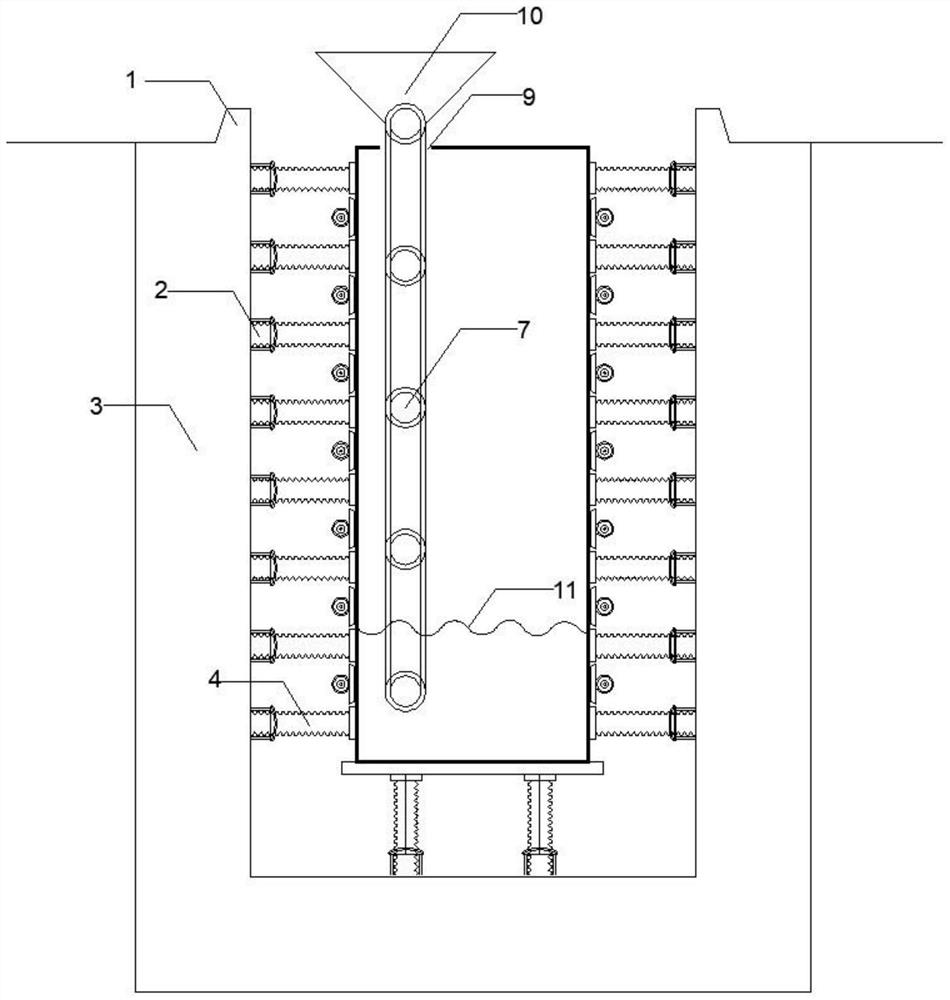
[0031] The present invention will be further described below in conjunction with specific embodiment, see Figure 1-Figure 3 , the invention provides a method for pouring concrete for a large ladle reinforced concrete protective door, which is a self-unloading vertical concrete pouring method for a large steel ladle reinforced concrete slab protective door, comprising the following construction steps:

[0032]1. Special fixed door slot 3: The special fixed door slot 3 is used as the fixed container for the ladle reinforced concrete protective door. The fixed door slot 3 is the core content of the present invention. The fixed door slot 3 is arranged below the ground and consists of a side wall, a bottom plate, a pre-embedded fixed fulcrum 2, an anti-collision safety pier 1, and an adjustable support base 8. The construction of the fixed door slot 3 should meet the following points: A. The bottom bearing capacity of the fixed door slot 3 should meet the requirements of bearing t...


PUM

PropertyMeasurementUnit
Thicknessaaaaaaaaaa
Heightaaaaaaaaaa
Diameteraaaaaaaaaa

Abstract

A concrete pouring method for a large steel ladle reinforced concrete protective door is suitable for filling construction of concrete in a door cavity of a steel ladle reinforced concrete flat protective door, a specially-made fixed door groove serves as a fixed container of the steel ladle reinforced concrete protective door, and the protective door is erected in the fixed door groove, conventional protective door concrete filling is transferred to the position below the ground from the ground, and a fixed door groove is matched with an adjustable reinforcing bolt for supporting, so that it is guaranteed that the protective door is in a horizontal state and a vertical state in the concrete pouring process; the compactness in the concrete pouring process is ensured by adopting an attached vibrator and a layered pouring method; concrete pouring is carried out in a simple self-discharging mode. Therefore, the pouring method adopts the self-unloading vertical concrete pouring method for the flat plate protective door, the steel door plate of the protective door is ensured not to deform in the whole concrete pouring process, the quality problem of cavity interlayer and door plate deformation generated when the protective door is horizontally poured is completely eradicated, and factory-like batch production and prefabrication can be realized.

Description

Technical field: [0001] The invention is mainly applied in the technical field of protective engineering, and is especially suitable for the construction of concrete filling inside the cavity of a large-scale steel-clad reinforced concrete protective door. Background technique: [0002] With the continuous development of national defense in our country, national defense engineering is becoming more and more important. At present, there are four common forms of large-scale protective doors in the field of protective engineering in my country: a, steel-clad steel tube concrete structure; b, steel-clad reinforced concrete structure; c, beam-slab structure beam-slab type; d, box-shaped steel plate + steel bar concrete composite structure. Among them, the ladle reinforced concrete structure has been widely used in recent years. [0003] After the traditional steel-clad reinforced concrete protective door is welded in the factory, the concrete is poured in a horizontal manner, an...

Claims


Application Information

Patent Timeline
IPC IPC(8): E04G21/02E04F21/00E06B3/70
CPCE04G21/02E04F21/0007E06B3/7015E06B2003/7028
Inventor 廖良胤邢铎陈军杨春钟辉李川徐云华苟万康陈翔王荣华
Owner SINOHYDRO BUREAU 7 CO LTD
Learn More