
Electric control actuator, tail gas treatment system and vehicle

An electric control actuator and exhaust gas treatment technology, which is applied in the direction of electric control, charging system, engine control, etc., can solve the problem that the electric control actuator is not finely laid out, the overall size of the electric control actuator is too large, and the internal installation Low space utilization and other issues, to achieve the effect of saving production costs, reducing assembly efficiency, and increasing assembly difficulty

Active Publication Date: 2022-02-08
NINGBO COLET ELECTRICAL APPLIANCE +1
View PDF7 Cites 1 Cited by
  • Summary
  • Abstract
  • Description
  • Claims
  • Application Information

AI Technical Summary

Problems solved by technology

[0004]However, in the prior art, the internal structure of the electric control actuator has not been finely laid out, that is, the utilization rate of the internal installation space is low. As a result, the overall size of the electric control actuators on the market is relatively large, so as to increase the internal installation space

Method used


Image

  • Electric control actuator, tail gas treatment system and vehicle
  • Electric control actuator, tail gas treatment system and vehicle
  • Electric control actuator, tail gas treatment system and vehicle

Examples


Embodiment 1

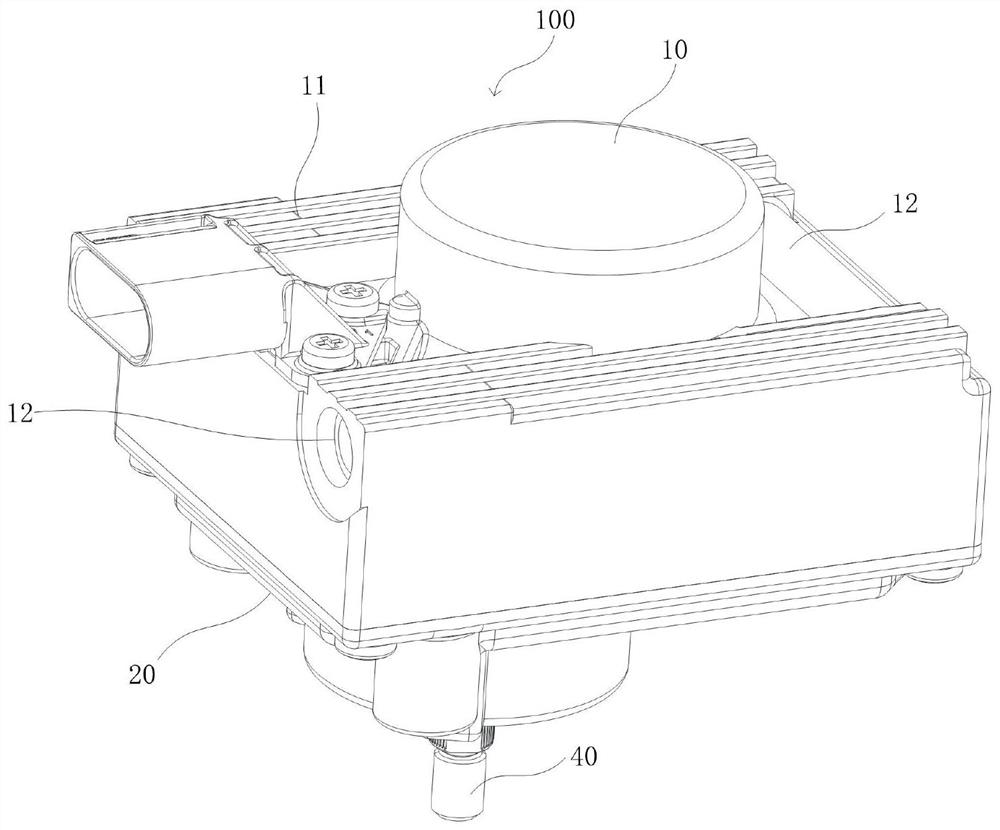
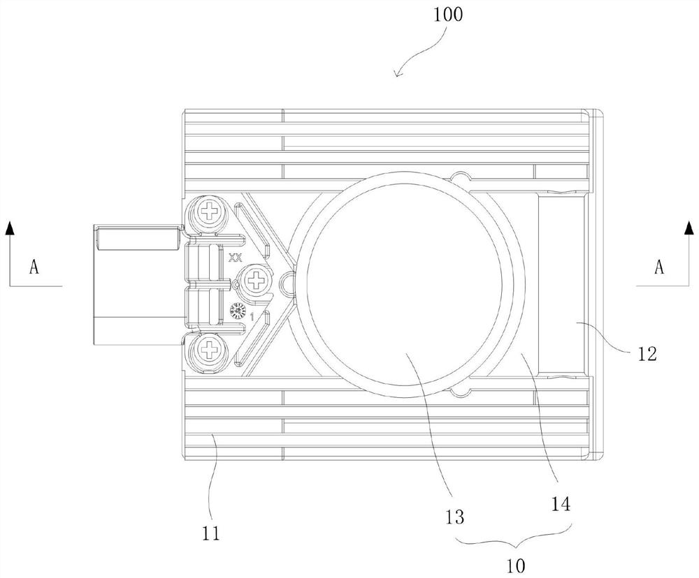
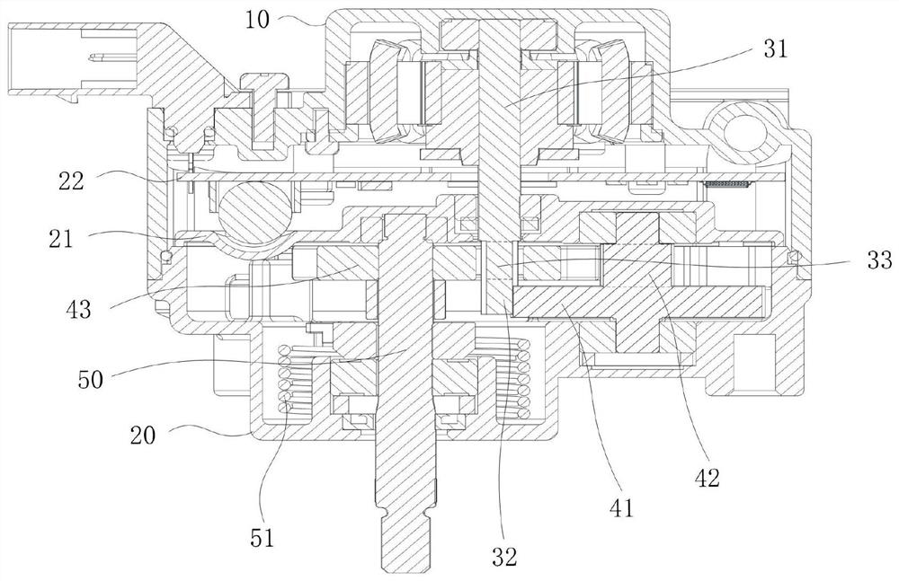
[0043] see figure 1 , which is a schematic structural diagram of an electronically controlled actuator 100 provided in Embodiment 1 of the present invention. The electric control actuator 100 includes, for example, a housing, a drive motor 30 and a compact gear assembly, wherein an installation space is provided in the housing, and the drive motor 30 and the compact gear assembly are all located in the installation space, and the compact gear assembly cooperates with the drive motor 30 Connection; the driving motor 30 is provided with a motor shaft 31, through which the transmission connection with the compact gear assembly can be realized.

[0044] combine Figure 2-Figure 5 Specifically, the compact gear assembly includes, for example, a first reduction gear 41 , a second reduction gear 42 and a sector gear 43 . The first reduction gear 41 is connected in transmission with the motor shaft 31; the second reduction gear 42 is coaxially fixedly connected with the first reduct...

Embodiment 2

[0063] Embodiment 2 of the present invention also provides an exhaust gas treatment system, for example, the exhaust gas treatment system includes the electronically controlled actuator 100 as described in Embodiment 1 above. Correspondingly, the technical effect corresponding to any one of the technical solutions in Embodiment 1 can be achieved, which will not be repeated here.

[0064] Preferably, the tail gas treatment system includes, for example, a valve, the valve is arranged on the exhaust gas circulation pipeline, and the electric control actuator 100 is used to control the opening or closing of the valve.

[0065] For example, the exhaust gas treatment system may be: a turbocharging system, an exhaust braking system, and an exhaust gas recirculation system.


PUM


Abstract

The invention provides an electric control actuator, a tail gas treatment system and a vehicle, the electric control actuator comprises a lower shell and an upper shell, and the lower shell or the upper shell is provided with a plurality of first matching holes; wherein the lower shell and the upper shell are matched to form a mounting space; the actuator further comprises an isolation plate which is clamped between the lower shell and the upper shell, and the isolation plate is provided with a plurality of second matching holes, wherein the first matching holes and the second matching holes are connected in a matched mode through positioning pieces; and a compact gear assembly and a driving motor arranged in the mounting space, wherein the compact gear assembly is connected with the driving motor in a matched mode. The electric control actuator solves the technical problem that the overall size of the electric control actuator is large due to the fact that the internal structure of the electric control actuator is not finely arranged.

Description

technical field [0001] The invention relates to the technical field of exhaust gas circulation of vehicles, in particular to an electronically controlled actuator, an exhaust gas treatment system and a vehicle. Background technique [0002] With the development of vehicle industry technology, electronically controlled actuators are an important part of vehicles, and electrical equipment has a certain impact on the development of the automobile industry. [0003] With the prospect of environmental protection and energy saving being paid more and more attention, the vehicle will install an exhaust gas circulation system at the engine. The electronic control actuator controls the opening of the valve at the exhaust gas circulation system, so that part of the exhaust gas enters the engine for re-combustion, thereby reducing the pollution of the exhaust gas to the environment and achieving the effect of energy saving. [0004] However, in the prior art, the internal structure of...

Claims


Application Information

Patent Timeline
Patent Type & Authority Applications(China)
IPC IPC(8): F02M26/53F02D41/00
CPCF02M26/53F02D41/0047F16K31/535F16K31/043F16K31/042F02M26/54F16K31/047F16K31/53
Inventor 吴冰何洲统王伟周开封张何
Owner NINGBO COLET ELECTRICAL APPLIANCE
Learn More