Closed impeller centrifugal pump

A closed impeller and centrifugal pump technology, applied in the direction of non-variable pumps, non-volume pumps, pumps, etc., can solve the problems of increased trouble in use or transfer work, high noise of cooling fan blades, and increased equipment load, etc. Achieve the effects of low noise, elimination of electric energy, and reduction of fan loading

Pending Publication Date: 2022-02-08
德二元(苏州)机电科技有限公司
View PDF0 Cites 0 Cited by
  • Summary
  • Abstract
  • Description
  • Claims
  • Application Information

AI Technical Summary

Problems solved by technology

[0003] However, in the subsequent application of circulating pumps for cooling and heating equipment, in order to facilitate the disassembly and assembly of centrifugal pumps, the impeller and motor were chosen to be installed separately, which indirectly increased the overall volume and caused more trouble in subsequent use or transfer work. Secondly, because the blades are installed on the output shaft of the motor to meet the heat dissipation, but the heat dissipation will increase the load of the overall equipment, and secondly, the noise generated by the cooling of the fan blades is relatively large

Method used


Image

  • Closed impeller centrifugal pump
  • Closed impeller centrifugal pump
  • Closed impeller centrifugal pump

Examples


Embodiment 1

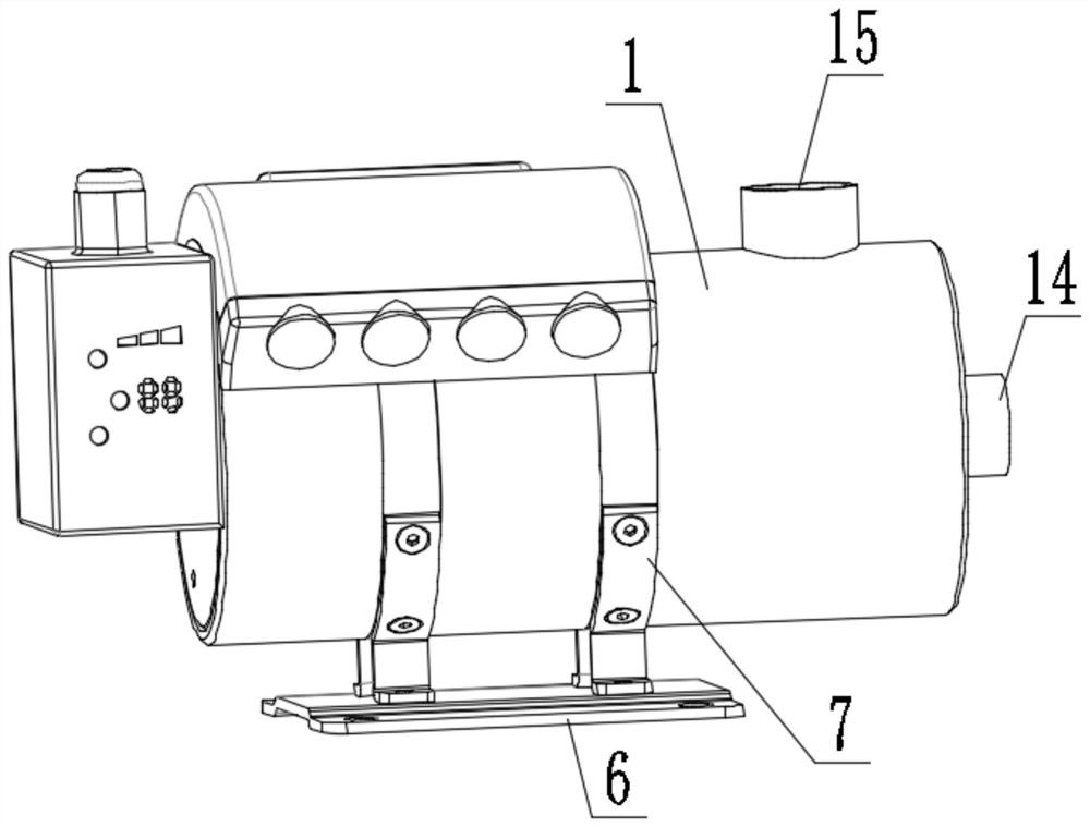
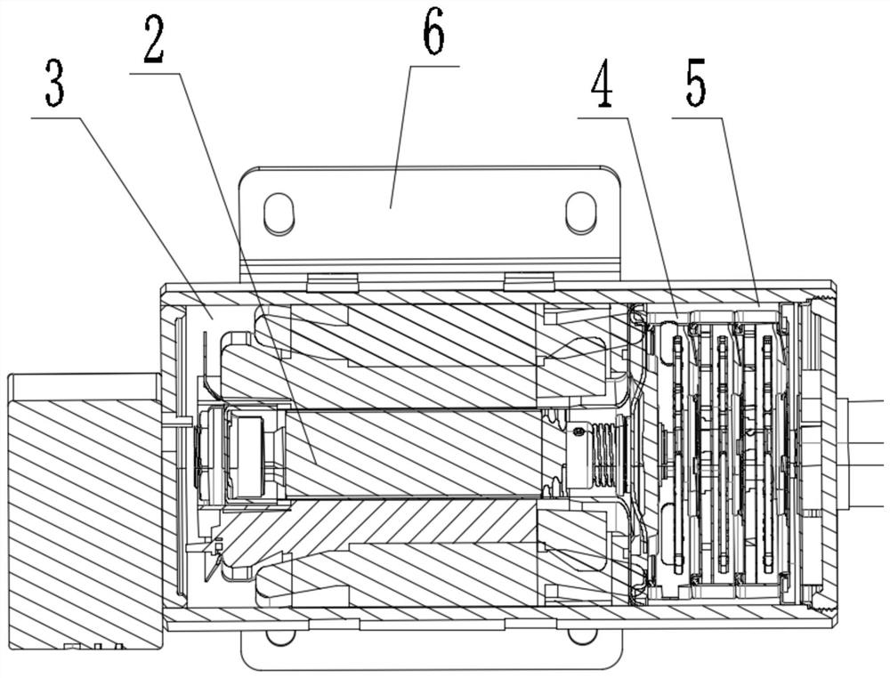
[0032] like figure 1 , figure 2 and Figure 8 , The present embodiment provides a closed impeller centrifugal pump, comprising a pump body, the pump body accommodating the impeller body has a first opening 4 of the body 5 in the cavity 1, the pump 1 has a further opening receiving the motor 2 second cavity 3, a spindle motor 2 through the second chamber 4 is connected to the impeller body 3 extends into the first chamber 5, the axis along which guide holes are opened on the rotating shaft, the One end of the second cavity of the guide hole 3 is turned on, the other end of the first cavity 5 is turned on, and close to the impeller 5 and the motor main body 2 between a first side of the cavity 4 having a shaft channel reserved space .

[0033] For application of the cooling, heating circulation pump equipment requirements, such as communications equipment 5G, wind power, robots, and other areas of the charging post, in order to solve this embodiment the impeller body 2 and the motor ...

Embodiment 2

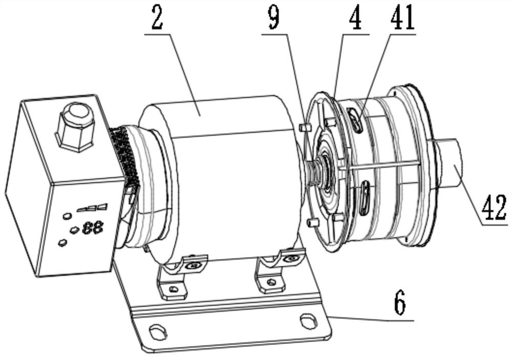
[0035] In this embodiment, on the basis of an embodiment of the launching, in response to the centrifugal pump efficiency of previously used relatively low problems, therefore the present embodiment is also designed in an end portion 4 of the spindle motor 2 to make improved impeller body, and at least two impeller body 4, such as Figure 4 , Figure 5 and Figure 7 As shown in particular by: a plurality of blades 4 in the impeller body 11, the adjacent guide grooves 12 constituting the clearance exists between the blades 11, a first flow chamber 5 flows into the impeller body under the action of centrifugal force 4, since the blades 11 and the outer periphery of the impeller body 12 into the guide groove of the water discharge pipe 4, outlet end located inwardly of the guide groove 12 formed recessed grooves 13, the adjacent guide grooves 12 communicates through the groove 13, which, as image 3 , On the impeller housing body 4 with a drain opening end 41, the particular shape may be...

Embodiment 4

[0038] This embodiment is based on the basis of Example 1, such as figure 1 As shown, a support base 6 is provided at the bottom of the pump body 1, and the top of the support base 6 is a semicircular curved structure, and a pump body of a semicircular arc-shaped portion is tightened by a pump body of a columnar body, a pump of a columnar body? The body 1 mates, the circular arc portion 7 of the base 6 is supported, the circular arc portion 7 is a semi-circular curved structure, so the circular arc portion 7 increases its contact area, which is not easy to fall off, followed by the motor 2 in the pump body 1. The blade of the impeller body 4 rotates, this process is vibrated, the structure can be well loaded, such as Image 6 As shown, the cone scroll 10 is inserted on the shaft of the motor 2, the cone scroll wheel 10 and the rotating shaft, and the magnetoelectric speed sensor 16 for detecting the shaft rotation speed is provided in the pump body 1. The magnetoelectric rotation s...


PUM


Abstract

The invention discloses a closed impeller centrifugal pump, relates to the technical field of circulating pumps, and solves the technical problems that existing equipment is large in size, and clearance oil leakage is generated between blades and an output shaft of a motor. The closed impeller centrifugal pump comprises a pump body, a first cavity for containing an impeller body is formed in the pump body, and a second cavity for containing the motor is further formed in the pump body; a rotating shaft of the motor penetrates through the second cavity and extends into the first cavity to be connected with the impeller body, a flow guide hole is formed in the axis of the rotating shaft along the axis of the rotating shaft, one end of the flow guide hole is communicated with the second cavity, the other end of the flow guide hole is communicated with the first cavity, and a reserved gap channel is formed between the first cavity and the motor. In order to eliminate noise generated by a fan in original equipment, the flow guide hole is selectively formed in the rotating shaft of the motor, a reserved gap channel is formed between the first cavity and the motor in a matched mode, the motor drives the impeller in the impeller body to rotate to generate hydraulic pressure difference, the motor is cooled in a cooling liquid circulation mode, and the cooling effect is achieved.

Description

Technical field [0001] Technical Field The present invention relates to a circulation pump, more particularly relates to the art closed impeller centrifugal pump. Background technique [0002] As one of the most widely used type of centrifugal pump works as follows: When the motor starts rotating to drive the pump impeller rotates at high speed in the water, water centrifugal movement, thrown outwards and pressed into outlet pipe, water is thrown back , the pressure near the impeller is reduced, the rotary shaft is formed in the vicinity of a low pressure zone, the pressure of the low pressure region is much lower than the atmospheric pressure outside of the water at atmospheric pressure effect, the impulse to open the bottom valve into the centrifugal pump inlet, rushed of water with high speed rotation of the impeller and is thrown, and pressed into the outlet pipe, an impeller continuously rotated at a high speed drive power machine, then a steady stream of water is pumped fro...

Claims


Application Information

Patent Timeline
Patent Type & Authority Applications(China)
IPC IPC(8): F04D13/06F04D29/62F04D29/043F04D29/58F04D29/66F04D29/04F04D29/22F04D29/24F04D29/42F04D1/08
CPCF04D13/0606F04D13/0646F04D29/628F04D29/043F04D29/5806F04D29/669F04D29/04F04D29/185F04D29/2222F04D29/2272F04D29/245F04D29/426F04D1/08
Inventor 金正辉
Owner 德二元(苏州)机电科技有限公司
Why Eureka
Try Eureka