Plate heat exchanger for white smoke removal system

A plate heat exchanger, whitening technology, applied in direct contact heat exchangers, heat exchanger types, indirect heat exchangers, etc., can solve the problem of increasing the amount of pipelines and floor space, and long distances between flue gas and air , Poor whitening effect and other problems, to achieve the effect of preventing liquid re-evaporation, reducing residence time, and improving total heat transfer coefficient

Pending Publication Date: 2022-02-08
南京宜热纵联环保科技溧阳有限公司
View PDF0 Cites 0 Cited by
  • Summary
  • Abstract
  • Description
  • Claims
  • Application Information

AI Technical Summary

Problems solved by technology

The existing dewhitening system for condensation and reheating is that the flue gas and air enter two pipes respectively after passing through the heat exchanger, and then mix and exhaust the flue gas later. This structure has the following disadvantages: 1. The flue gas and air pass through the heat exchanger After coming out of the device, it enters two pipes, and then enters the chimney after mixing, resulting in an increase in the amount of pipes and floor space, resulting in waste; 2. The air inlet and the flue gas outlet exchange heat. At this time, the flue gas still contains a large number of liquid droplets. Bringing it into the chimney, resulting in poor whitening effect; 3. The flue gas and air pass through a long distance, resulting in large system resistance and high operating costs

Method used


Image

  • Plate heat exchanger for white smoke removal system
  • Plate heat exchanger for white smoke removal system
  • Plate heat exchanger for white smoke removal system

Examples


Embodiment Construction

[0014] Attached below Figure 1-5 The technical scheme of the present invention will be further described.

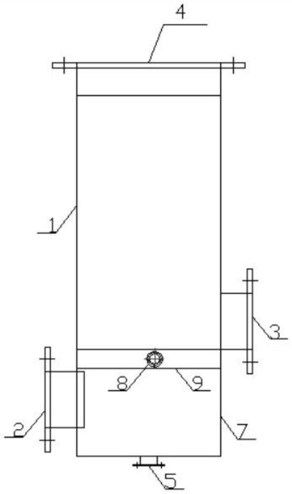
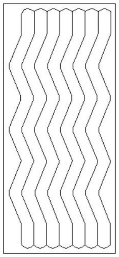
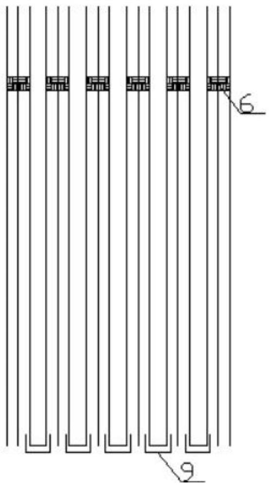
[0015] As shown in the figure, a plate heat exchanger for dewhitening system includes a hot cavity 1 located in the middle of the heat exchanger, a flue gas inlet pipe 2 located below the hot cavity 1, a flue gas duct 7 and The mixed gas outlet 4 is located above the hot cavity 1, and the inside of the hot cavity 1 is a heat exchange core, which is composed of molded corrugated rectangular heat exchange plates arranged in parallel; the middle and lower part of the thermal cavity 1 is provided with useful In addition to the defoaming screen 6 for blocking liquid droplets, the bottom of the flue gas duct 7 is provided with a liquid discharge port 5, and the lower part of the heat exchange core is provided with a liquid collection tank 9 for collecting condensate.

[0016] The heat exchange fin has a corrugated structure along the length, so that the flue gas channel is f...


PUM


Abstract

The invention discloses a plate heat exchanger for a white smoke removal system. The plate heat exchanger comprises a hot cavity positioned in the middle of the heat exchanger, a flue gas inlet pipeline positioned below the hot cavity, a flue gas duct and a mixed gas outlet positioned above the hot cavity; a heat exchange core is inside the hot cavity, the heat exchange core is composed of mould pressing corrugated rectangular heat exchange plates which are arranged in parallel; a defoaming wire mesh used for blocking liquid drops is arranged on the lower middle portion of the hot cavity, a liquid outlet is formed in the bottom of the flue gas duct, and a liquid collecting groove used for collecting condensate is formed in the lower portion of the heat exchange core. The heat exchange plates are folded, so that flue gas and air are mixed after heat exchange, and the mixing uniformity is guaranteed; the flue gas channel is corrugated, and condensate is downwards injected into the liquid collecting tank along the corrugated channel, so that liquid evaporation is prevented; a demister is used for dehumidification; by adjusting the height of folded edges and adjusting the distance between flue gas and air, the air flow speed is increased, the single-side heat transfer film coefficient of the air side is increased, and the total heat transfer coefficient of the heat exchanger is increased.

Description

technical field [0001] The invention relates to a heat exchanger, in particular to a plate heat exchanger used in a whitening system. Background technique [0002] With the continuous development and progress of China's economy, the demand for energy is increasing day by day. Among them, coal and oil are the most important combustion energy in China. Although they meet the needs of economic development, they have caused major environmental pollution, especially sulfur dioxide pollution. Most of the gas purification and treatment technologies adopt the limestone-gypsum wet desulfurization process. The clean flue gas with saturated water at the outlet of the absorption tower is partially condensed to form liquid droplets during the discharge process from the chimney, and the moisture in the flue gas cannot be effectively diffused into the atmosphere. When the relative humidity of the air is high and the temperature is low, the moisture content of the atmosphere is close to sat...

Claims


Application Information

Patent Timeline
Patent Type & Authority Applications(China)
IPC IPC(8): F28D9/00F28C3/02F28F3/02F28F17/00F28F19/00
CPCF28D9/0037F28C3/02F28F3/025F28F17/005F28F19/00
Inventor 杨西钱荣忠朱国富李俊陈华斌
Owner 南京宜热纵联环保科技溧阳有限公司
Why Eureka
Try Eureka