Industrial automatic control system cabinet

An automatic control system and industrial technology, which is applied in the direction of electrical components, substation/distribution device casing, substation/switchgear cooling/ventilation, etc. Performance and other issues to achieve the effect of reducing the impact of climate, accelerating heat dissipation, and improving performance

Pending Publication Date: 2022-02-08
赵维盛
View PDF0 Cites 0 Cited by
  • Summary
  • Abstract
  • Description
  • Claims
  • Application Information

AI Technical Summary

Problems solved by technology

[0005] Aiming at the deficiencies of the prior art, the present invention provides an industrial automatic control system cabinet, which solves the problem that the traditional industrial automatic control system cabinet is easily affected by the climate, especially during the rainy season in the south, the electric control cabinet is under high temperature and humidity. In the environment, condensation and water droplets are easily produced on the inner wall of the electric control cabinet, and the internal electrical appliances are prone to short circuit when exposed to water, which seriously affects the normal operation of electrical equipment, and even paralyzes the entire equipment, reducing the performance

Method used


Image

  • Industrial automatic control system cabinet
  • Industrial automatic control system cabinet
  • Industrial automatic control system cabinet

Examples


Embodiment example 1

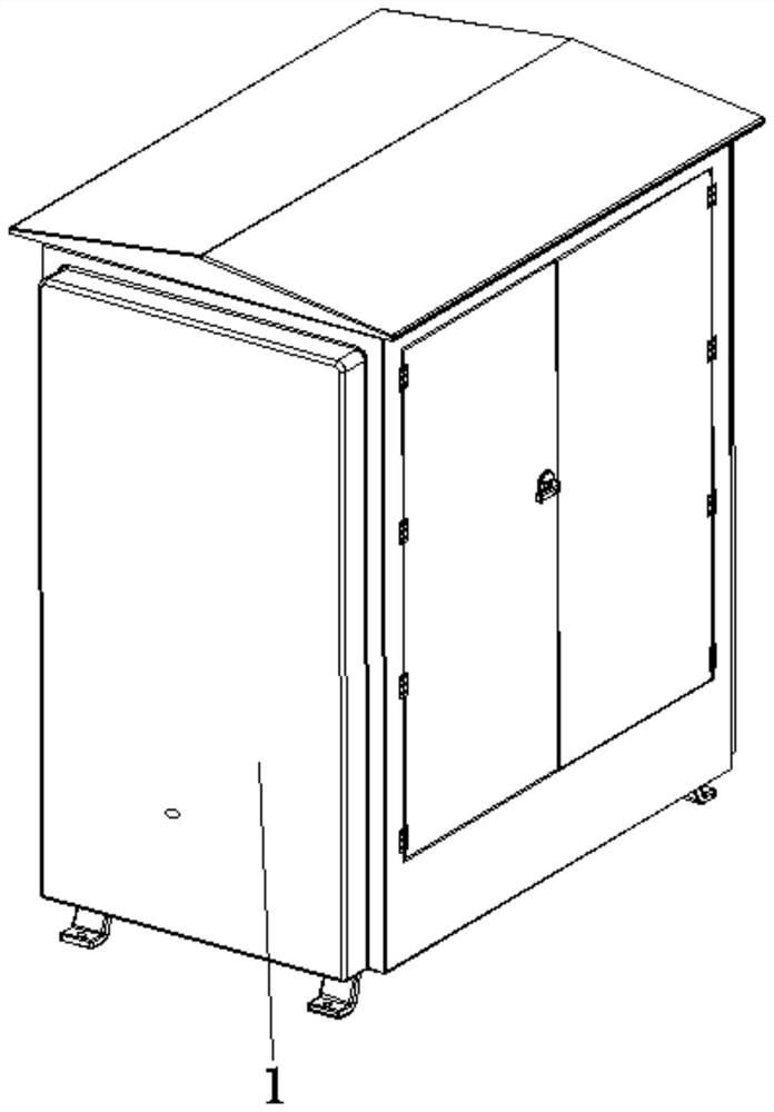
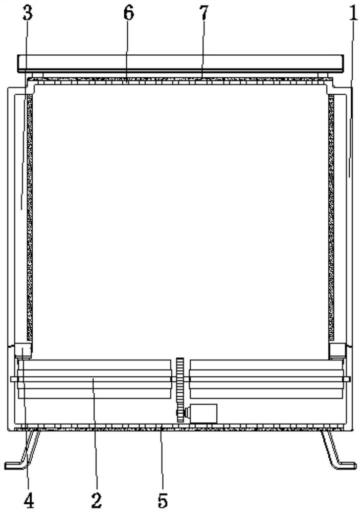
[0031] see Figure 1-7 , the present invention provides a technical solution: an industrial automatic control system cabinet, including a cabinet body 1, the interior of the cabinet body 1 is provided with a heat dissipation device 2, a suction device 3, a pressing device 4, an air inlet hole 5, and an air outlet hole 6 , dust filter screen 7, heat dissipation device 2 is rotatably connected between the two sides corresponding to the inner wall of cabinet body 1 and near the bottom position, suction device 3 is arranged on the inner wall of cabinet body 1, pressing device 4 is arranged on the inner wall of cabinet body 1 and Located at the bottom of the suction device 3, the air inlet hole 5 is set at the bottom of the cabinet body 1, the air outlet hole 6 is set at the top of the cabinet body 1, and the dust filter 7 is set at the top and bottom of the cabinet body 1 and located at the air inlet hole 5. The position of the air outlet 6 can reduce the dust from entering the in...

Embodiment example 2

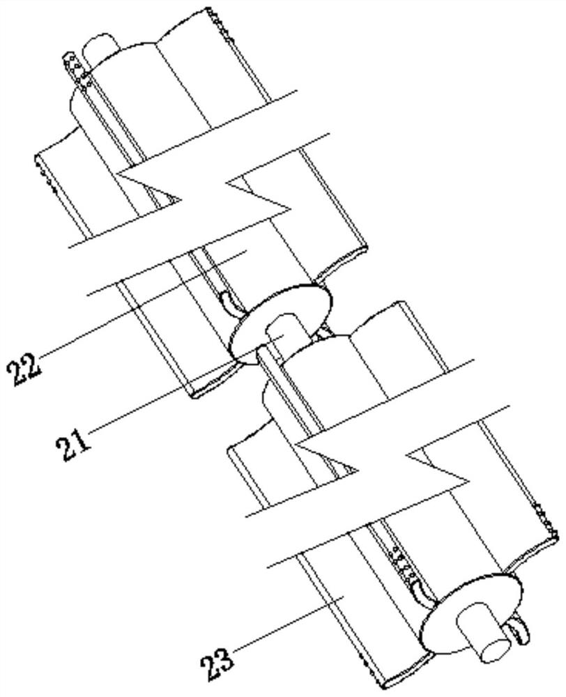
[0033] The cooling device 2 is provided with a rotating shaft 21, a drum 22, and a fan blade device 23. The two ends of the rotating shaft 21 are rotationally connected to the two sides corresponding to the inner wall of the cabinet body 1. The drum 22 is fixedly connected to the surface of the rotating shaft 21 and is close to the end position. The device 23 is fixed on the surface of the drum 22, and the end of the fan blade device 23 is connected with the bottom of the pressing device 4. After the rotating shaft 21 is driven by the motor, the drum 22 drives the fan blade device 23 to rotate, and the blade device 23 is rotated in time. The air inside the cabinet 1 is instigated, and through the flow of gas, the heat is dissipated from the air outlet 6, and at the same time, the external cold air enters from the air inlet 5, thus forming an air convection cycle, which accelerates the heat dissipation. It reduces the occurrence of high temperature, accelerates evaporation, and ...

Embodiment example 3

[0036] The suction device 3 is provided with a base plate 31, a water-absorbing sponge body 32, a main channel 33, and a horn hole 34. One side of the surface of the base plate 31 is fixedly connected with the inner wall of the cabinet body 1, and the water-absorbing sponge body 32 is arranged on the surface of the base plate 31 and is far away from the cabinet body. 1, the main channel 33 is opened inside the base plate 31, the bottom end of the main channel 33 is connected with the pressing device 4, the horn hole 34 is opened on the inner wall of the base plate 31 and is located at the position of the water-absorbing sponge body 32 and is connected with the The main channel 33 is connected, and the water-absorbing sponge body 32 can absorb the condensation and water droplets in the cabinet 1 in time, and reduce the rotation of the fan blade device 23, so that the pressing device 4 can work. The water on the water-absorbing sponge body 32 is quickly absorbed from the horn hol...


PUM


Abstract

The invention discloses an industrial automatic control system cabinet, which comprises a cabinet body; a heat dissipation device, a suction device, a pressing device, an air inlet hole, an air outlet hole and dust filter screens are arranged in the cabinet body; the heat dissipation device is rotatably connected between two corresponding sides of the inner wall of the cabinet body and is close to the bottom position; the suction device is arranged on the inner wall of the cabinet body; the pressing device is arranged on the inner wall of the cabinet body and located at the bottom of the suction device; the air inlet hole is formed in the bottom of the cabinet body, and the air outlet hole is formed in the top of the cabinet body; and the dust filter screens are arranged at the top and the bottom of the cabinet body and located at the air inlet hole and the air outlet hole. The invention relates to the technical field of electrical equipment. According to the industrial automatic control system cabinet, the purpose of moisture prevention is achieved, the influence of weather is reduced, and condensation and water drops can be sucked in time, so that the situation of short circuit is not prone to occurring, the service life of components is prolonged, and the use performance is improved.

Description

technical field [0001] The invention relates to the technical field of electric equipment, in particular to an industrial automatic control system cabinet. Background technique [0002] Electric control cabinet is to assemble switchgear, measuring instrument, protective device and auxiliary equipment in closed or semiclosed metal cabinet or on screen width according to electrical wiring requirements, and its layout should meet the requirements of normal operation of power system, and is easy to overhaul and does not endanger people. Safe control cabinet for personal and surrounding equipment. With the further development of society, automation is more and more applied to all aspects of our life and production, especially in industrial production. The whole world is upgrading to Industry 4.0, which greatly speeds up the development of automation. The development of automation is inseparable from the electric control cabinet. The electric control cabinet is the brain center ...

Claims


Application Information

Patent Timeline
IPC IPC(8): H02B1/56H02B1/28H02B1/30H02B1/32
CPCH02B1/565H02B1/28H02B1/303H02B1/306H02B1/32
Inventor 赵维盛
Owner 赵维盛
Why Eureka
Try Eureka