
Stamping, bending and welding equipment

A stamping bending and welding equipment technology, applied in welding equipment, auxiliary welding equipment, welding/cutting auxiliary equipment, etc., can solve problems such as damage to the health of operators, generation of harmful gases, low production efficiency, etc., and achieve the goal of improving processing Efficiency, efficiency improvement, and effect of reducing processing steps

Inactive Publication Date: 2022-02-11
蔡瑞凡
View PDF0 Cites 3 Cited by
  • Summary
  • Abstract
  • Description
  • Claims
  • Application Information

AI Technical Summary

Problems solved by technology

[0004] The purpose of the present invention is to solve the problems in the prior art that harmful gases are often generated when the plates are welded, which has damaged the health of the operators for a long time, and the workers need to remove slag and polish them after welding. process, resulting in time-consuming and labor-intensive shortcomings, and low production efficiency, and a stamping bending welding equipment proposed

Method used


Image

  • Stamping, bending and welding equipment
  • Stamping, bending and welding equipment
  • Stamping, bending and welding equipment

Examples


Embodiment 1

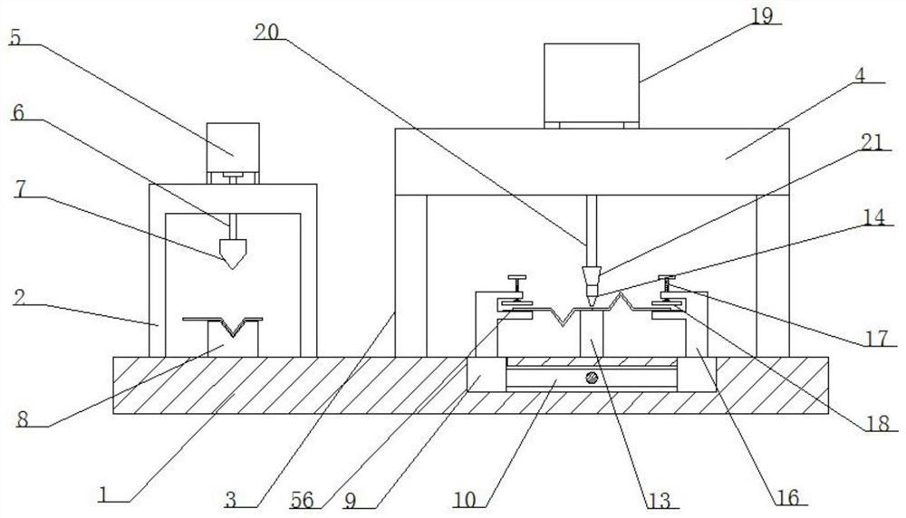
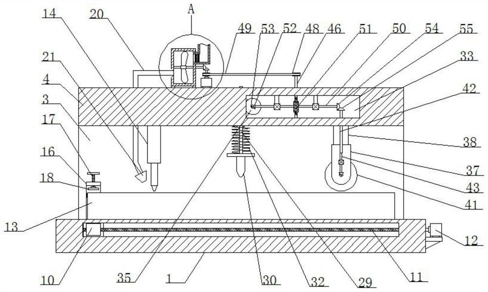
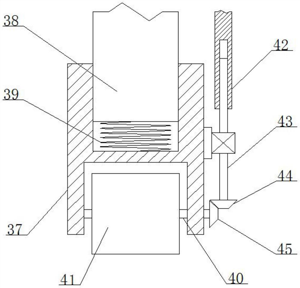
[0031] refer to Figure 1-7, a stamping bending welding equipment, including a base plate 1, the top of the base plate 1 is fixedly connected with a U-shaped frame 2 and two side plates 3 by welding, and the top of the two side plates 3 is fixedly connected with the same top plate 4 by welding, The top of the U-shaped frame 2 is fixed with a hydraulic press 5 by bolts, the output shaft of the hydraulic press 5 is provided with a telescopic rod 6, the bottom end of the telescopic rod 6 is fixedly connected with a stamping and bending block 7 by welding, and the top of the bottom plate 1 is provided with a stamping The base 8, the stamping and bending block 7 cooperate with the stamping base 8, and the top of the bottom plate 1 is provided with two slider grooves, and a slider 9 is slidably installed in the two slider grooves, and the two slider grooves are close to each other. One side is provided with the same sliding through groove, and a cross bar 10 is slidably installed in...

Embodiment 2

[0043] The difference from Embodiment 1 is that the clamping mechanism includes an F-shaped plate element 16 fixedly installed on the top of the slider 9, the top of the F-shaped plate element 16 is provided with a bolt 17, and the bottom end of the bolt 17 is fixedly connected with a clamping On the plate 18 , the F-shaped plate element 16 is provided with a rubber gasket 56 .

[0044] In the present invention, when in use, the hardware sheet is first placed on the stamping base 8, and then the hydraulic press 5 is started, so that the hydraulic press 5 stamps and bends the hardware sheet into a desired shape through the telescopic rod 6 and the stamping and bending block 7, and then Install the finished two metal plates on the two clamping mechanisms, turn the bolt 17 so that the bolt 17 passes through the clamping plate 18 to clamp and fix the hardware plate on the F-shaped plate element 16, and the F-shaped plate element 16 passes through The rubber spacer 56 can effective...


PUM


Abstract

The invention belongs to the field of hardware plate machining, particularly relates to stamping, bending and welding equipment, and aims to solve the problems that harmful gas is often generated when existing plates are welded, the body health of operators is damaged for a long time, a plurality of procedures such as deslagging and polishing need to be carried out on the plates by workers after welding, time and labor are wasted, and the production efficiency is poor. According to the technical scheme, the equipment comprises a bottom plate, the top of the bottom plate is fixedly connected with a U-shaped frame and two side plates, the tops of the two side plates are fixedly connected with the same top plate, the top of the U-shaped frame is fixedly provided with a hydraulic machine, and an output shaft of the hydraulic machine is provided with a telescopic rod. During use, harmful gas can be effectively filtered, purified and discharged, meanwhile, welding slag generated by welding can be continuously removed after welding is completed, finally, exposed welding seams are polished and ground, the machining procedures after welding are effectively reduced, and the machining efficiency is improved.

Description

technical field [0001] The invention relates to the technical field of metal plate processing, in particular to a stamping, bending and welding equipment. Background technique [0002] At present, in metal plate processing and other industries, it is usually necessary to go through multiple processes when processing a piece of hardware. The more common processing methods are stamping, bending and welding. At present, the processing of hardware is usually processed by equipment, such as Bending and welding equipment can effectively improve processing efficiency; [0003] However, in the existing technology, harmful gases are often generated when the stamped and bent plates are welded, which has long damaged the health of the operator, and after welding, the staff needs to perform multiple processes such as slag removal and polishing. , resulting in time-consuming and labor-intensive, low production efficiency. Contents of the invention [0004] The purpose of the present ...

Claims


Application Information

Patent Timeline
Patent Type & Authority Applications(China)
IPC IPC(8): B23P23/00B01D53/04B23K37/08
CPCB23P23/00B01D53/04B23K37/08B01D2253/102
Inventor 蔡瑞凡
Owner 蔡瑞凡
Learn More