Eureka AIR delivers breakthrough ideas for toughest innovation challenges, trusted by R&D personnel around the world.

Liquid fuel nozzle for dual-radial swirler dual-fuel combustion chamber

A liquid fuel and swirler technology, applied in combustion chambers, continuous combustion chambers, combustion methods, etc., can solve the problems of poor premixed combustion stability, high diffusion combustion emissions, and ensure efficient and stable combustion, efficient and stable combustion, The effect of preventing coking

Pending Publication Date: 2022-02-11
东方电气集团科学技术研究院有限公司
View PDF7 Cites 0 Cited by
  • Summary
  • Abstract
  • Description
  • Claims
  • Application Information

AI Technical Summary

Problems solved by technology

[0007] The purpose of the present invention is to solve the technical problems that the combustor of a dual-fuel gas turbine burns liquid fuel with high diffusion combustion, poor stability of premixed combustion, and difficulty in achieving premixed matching with traditional centrifugal nozzles and vortexers, and provides a A liquid fuel nozzle for a dual-radial vortex dual-fuel combustion chamber, through a reasonable structural design, can achieve efficient and stable combustion while achieving efficient evaporation and mixing of liquid fuel, and reduce the NOx in the combustion chamber x Emissions, achieving a good balance between flameout performance and low emissions

Method used


Image

  • Liquid fuel nozzle for dual-radial swirler dual-fuel combustion chamber
  • Liquid fuel nozzle for dual-radial swirler dual-fuel combustion chamber
  • Liquid fuel nozzle for dual-radial swirler dual-fuel combustion chamber

Examples


Embodiment 1

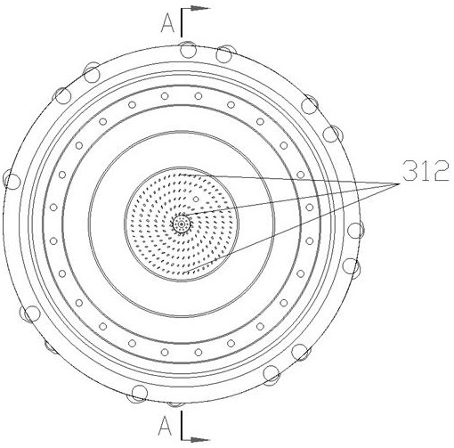
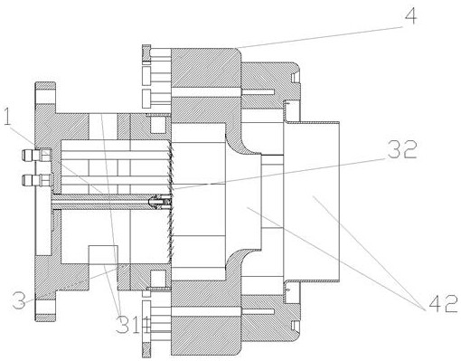
[0058] like Figure 1-4 As shown, a liquid fuel nozzle for a double diameter turntorm dual fuel combustion chamber comprises a crime-level nozzle 1, a primary fuser 2, a front mounting section 3, a vortex 4, and the above zero component is assembled into a whole, Complete atomization evaporation of the burner head fuel.

[0059] Specifically, the front mounting section 3 includes a front mounting segment front section 31 and a rear segment, the front end of the turntorm 4 fixed to the rear segment of the front mounting section 3, and the value-class nozzle 1 is mounted on the center axis of the front mounting section 3, on duty Level nozzle 1 is connected to the vortex throat 42; the front end surface of the eddy current collector 4 is arranged centrally to the center circumference, and the main stage spray rod 2 is arranged, and the main stage sprinkler 2 is connected to the vortex blade passage 41. The front mounting section 3 and the contact surface of the turntorm 4 are the fro...

Embodiment 2

[0063] like Figure 5-7 As shown, on the basis of Example 1, the value class nozzle 1 includes a swirl core 11, a spray tube 12, a crime-level nozzle cooling cover 13, a crime-level nozzle rod 14, a crime-level nozzle rod 14 is mounted in a swirling flow The top of the core 11, the tail end set of the swirl core 11, the outer sleeve of the spray tube 12, the outer sleeve 13; the top of the value class nozzle rod 14 is a crime-level fuel inlet 111, a crime-level nozzle rod 14 The center is axially in a crime-level fuel flow path, and the tail of the spray tube 12 is funnel shape, and the bottom of the funnel is nozzle 114.

[0064] The cyclone core 11 includes a top, intermediate cylindrical segment, and a bottom end, and the top is tapered or spherical, the top and the criterioned nozzle rod 14 forms a tapered or spherical sealing structure, the intermediate of the top and the cylindrical segment. The hollow structure, the bottom of the cylindrical section is the end surface of the...

Embodiment 3

[0070] like Figure 8-9 As shown, on the basis of Example 1 or 2, the axial intermediate of the main fuel spray rod is the main fuel-grade fuel flow path, one end of the main burn-fuel-fuel flow path is the main stage sprinkler fuel inlet 211, another One end is the main fuel outlet; the sidewall of the main fuel spray rod is provided with several major fuel spray rods 212 for the main burn-fuel flow inflow, and the main fuel spray rod spout 212 is associated with the main stage 2 The main level fuel flow in the middle is connected.

[0071] The main bonded fuel is inflows from the primary fuel inlet 211 on the main fuel spray rod, and the main fuel spray rod spout 212 takes a simple hole pressure atomization method to obtain an initial homoa oil cone that satisfies the requirements, and sprayed with eddy current. The blade passage 41.

[0072] The main burn-fuel fuel and the eddy current collector 4 cooperate Figure 10-12 As shown, by using the structure of the open inclined hole ...


PUM


Abstract

The invention discloses a liquid fuel nozzle for a dual-radial swirler dual-fuel combustion chamber, which comprises an on-duty stage nozzle, a main stage spray rod, a front mounting section and a swirler, the front end of the swirler is connected with a front mounting section, the on-duty stage nozzle is mounted on the central axis of the front mounting section, and the on-duty stage nozzle is communicated to a swirler throat; a plurality of main-stage spray rods are circumferentially arranged on the front end face of the swirler with the front mounting section as the center, and spray holes of the main-stage spray rods are communicated to a swirler blade channel; the on-duty stage nozzle is mainly used for supplying fuel oil to a diffusion combustion flame-stabilizing oil path; the main stage spray rod is mainly used for supplying liquid fuel and gas fuel for premixed combustion, and the liquid fuel and the gas fuel are injected to form good initial atomization and form good mixing evaporation matching with airflow of the swirler at the same time. By means of the reasonable structure, efficient and stable combustion can be achieved while efficient evaporation and mixing of liquid fuel are achieved, NOx emission of a combustion chamber is reduced, and good consideration of flameout performance and low emission is achieved.

Description

Technical field [0001] The present invention relates to the technical field of gas turbines, particularly a liquid fuel nozzle for a double-diameter turntorm dual fuel combustion chamber. Background technique [0002] A double fuel gas turbine refers to a gas turbine of liquid / gas fuel simultaneously using double fuel combustion techniques. By implementing dual fuel combustion technology in a gas turbine, it is possible to improve the adaptability of the gas turbine on the fuel, and broaden the field of gas turbine applications. Therefore, it has developed a high-performance dual-fuel gas turbine with more fuel adaptability, expands the field of gas turbine applications, and has become one of the new development directions of gas turbine. [0003] The double fuel combustion chamber is a core component of a dual fuel gas turbine. When combustion of liquid and gas fuel, it has good performance, and the most important point is to take care of the point off and emission performance...

Claims


Application Information

Patent Timeline
IPC IPC(8): F23R3/38F23R3/34
CPCF23R3/38F23R3/346
Inventor 唐豪杰范珍涔关雪丰赵庆吴家桦
Owner 东方电气集团科学技术研究院有限公司
Why Eureka
Eureka Blog
Learn More