Filter with particulate matter separation function for oil field demulsifier production

A technology of demulsifier and particulate matter, which is applied in the field of filters with particle separation function for the production of demulsifier in oilfields, and can solve the problems of inconvenient discharge of particulate impurities from the filter device, reducing the filter device, and reducing the filtration efficiency of the demulsifier.

Active Publication Date: 2022-02-15
东营市宝泽能源科技有限公司 +1
View PDF7 Cites 15 Cited by
  • Summary
  • Abstract
  • Description
  • Claims
  • Application Information

AI Technical Summary

Problems solved by technology

[0005] In order to overcome the disadvantages that the separated particulate impurities are not convenient to be discharged from the filter device, reduce the normal use of the filter device, and reduce the filtration efficiency of the demulsifier, the technical problem to be solved is to provide a filter with particle separation function for the production of demulsifiers in oil fields

Method used


Image

  • Filter with particulate matter separation function for oil field demulsifier production
  • Filter with particulate matter separation function for oil field demulsifier production
  • Filter with particulate matter separation function for oil field demulsifier production

Examples


Embodiment 1

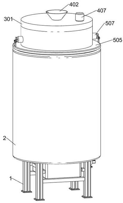
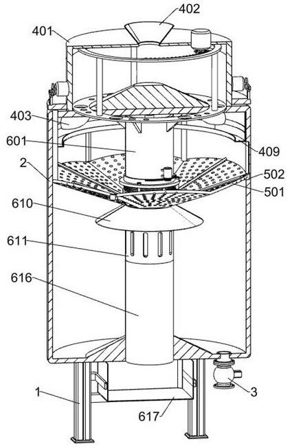
[0036] A filter with particle separation function for oilfield demulsifier production, such as Figure 1-13 As shown, it includes a bracket 1, a support shell 2, a solenoid valve 3, a feeding mechanism, a vibration filter mechanism, a cleaning mechanism and a slag discharge mechanism. The upper end of the bracket 1 is fixedly connected with a support shell 2, and the inner bottom of the support shell 2 is a The right part of the lower side of the support shell 2 is connected with a solenoid valve 3, the lower end of the solenoid valve 3 is connected with a water pump, and the feeding mechanism is set above the support shell 2, which is a vibration filter mechanism for filtering demulsifiers in oil fields. Located on the inner surface of the support shell 2, the cleaning mechanism for cleaning the filtered particulate impurities is located on the upper inner surface of the support shell 2, the vibrating filter mechanism cooperates with the cleaning mechanism to clean the slag of...

Embodiment 2

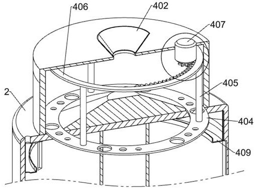
[0039] On the basis of Example 1, such as Figure 2-13 As shown, the feeding mechanism includes a material holding shell 401, a first conical shell 402, a discharge pipe 403, a first rotating ring 404, a first connecting rod 405, a second rotating ring 406, a first servo motor 407, and a second rotating ring 406. A gear 408 and a circular groove plate 409, the material holding case 401 is fixedly connected to the top of the support case 2, the inner bottom of the material holding case 401 is provided with conical protrusions, and the first conical shell 402 is connected to the bottom of the holding material case 401 Above, the lower side of the material holding shell 401 is connected with six discharge pipes 403 at equal intervals along its circumference. At the lower part of the side, the first rotating ring 404 is sealingly matched with the material housing 401. The first rotating ring 404 is provided with six groups of circular through holes along its circumference, and eac...

Embodiment 3

[0050] On the basis of Example 2, such as Figure 14 with Figure 15 As shown, it also includes an anti-adhesion mechanism. The anti-adhesion mechanism includes a second conical shell 801, a fixed plate 802, a square shell 803, a second spring 804, a square baffle plate 805, a sixth servo motor 806 and a cam 807. Two conical shells 801 are affixed to the top of the inner surface of the second fixed shell 616, and the upper and lower parts of the inner surface of the second fixed shell 616 are symmetrically fixed with fixed plates 802 front and rear, and a square shell 803 is slidably connected between the four fixed plates 802 , the left and right sides of the outer side of the square shell 803 are respectively fixed with several second springs 804, and the lower sides of the two fixed plates 802 on the front side are respectively provided with two square baffles 805, and the square baffles 805 are fixed to the square shell 803, the lower sides of the two fixed plates 802 on ...


PUM


Abstract

The invention relates to the technical field of demulsifier production, in particular to a filter with a particulate matter separation function for oil field demulsifier production. The technical problems that separated particle impurities are inconvenient to discharge out of a filtering device, normal use of the filtering device is reduced, and the filtering efficiency of a demulsifier is reduced are solved. According to the technical scheme, the filter with the particulate matter separation function for oil field demulsifier production comprises a supporting shell, a feeding mechanism, a vibration filtering mechanism and the like, the inner side face of the bottom of the supporting shell is provided with a protrusion, the feeding mechanism is arranged above the supporting shell, and the vibration filtering mechanism is arranged on the upper portion of the inner side face of the supporting shell. By designing the feeding mechanism, non-uniform discharging of an oil field demulsifier caused by different pressures of the oil field demulsifier to the bottom of the material containing shell is avoided, by designing the vibration filtering mechanism, the filtering efficiency of the sieve plate is improved, and meanwhile, the situation that too many impurity particles are accumulated, and filtering holes in the sieve plate are blocked is avoided.

Description

technical field [0001] The invention relates to the technical field of demulsifier production, in particular to a filter with particle separation function for oilfield demulsifier production. Background technique [0002] The demulsifier is obtained by the polymerization of fatty alcohol, propylene oxide, and ethylene oxide. It is easily soluble in water and is a light yellow or milky white viscous liquid. It is an oilfield chemical agent for oil-water separation of oil production fluid. The emulsion goes deep and adheres to the interface of the emulsified droplets, replaces the original emulsifier and destroys the surface film, releases the droplets wrapped in the film and makes them coalesce, so that the oil and water phases are separated, and the emulsion can be destroyed of surfactants. [0003] The demulsifier may form a suspension during the preparation process. There will be a large number of suspended particles in the suspension. The existence of suspended particles...

Claims


Application Information

Patent Timeline
Patent Type & Authority Applications(China)
IPC IPC(8): B01D33/03B01D33/37B01D33/46B01D33/72B01D33/76
CPCB01D33/0353B01D33/37B01D33/72B01D33/76B01D33/46
Inventor 聂中祥王中鹏吕本增李长清张坤宋彬
Owner 东营市宝泽能源科技有限公司
Why Eureka
Try Eureka