Eureka AIR delivers breakthrough ideas for toughest innovation challenges, trusted by R&D personnel around the world.

Magnetorheological fluid soft die forming method and device for deep-cavity thin-wall component

A magnetorheological fluid and thin-walled component technology, applied in the field of sheet metal forming, can solve problems such as difficulty and complex magnetic field regulation procedures in different regions, achieve good deformation, good application prospects, and solve the effects of complex regulation procedures

Inactive Publication Date: 2022-02-15
SHAANXI UNIV OF SCI & TECH
View PDF1 Cites 2 Cited by
  • Summary
  • Abstract
  • Description
  • Claims
  • Application Information

AI Technical Summary

Problems solved by technology

[0005] In order to solve the above problems, the present invention provides a magnetorheological fluid soft mold forming method and device for deep-cavity thin-walled parts, which can solve the complicated and difficult magnetic field control procedures in different regions in the current soft mold forming of deep-cavity thin-walled parts. problems, alleviate excessive wall thickness reduction during the forming process, and improve the forming quality of deep cavity thin-walled components

Method used


Image

  • Magnetorheological fluid soft die forming method and device for deep-cavity thin-wall component
  • Magnetorheological fluid soft die forming method and device for deep-cavity thin-wall component
  • Magnetorheological fluid soft die forming method and device for deep-cavity thin-wall component

Examples


Embodiment 1

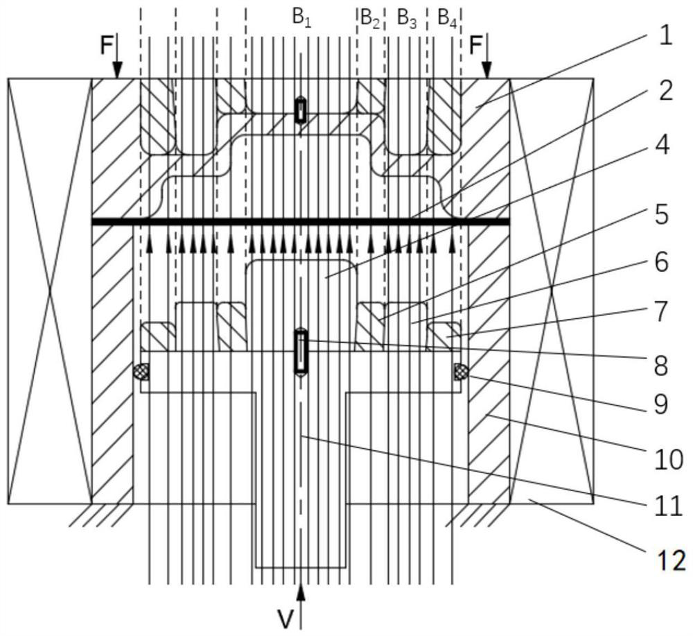
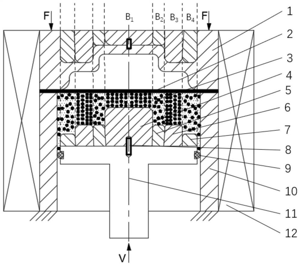
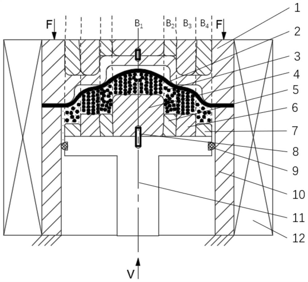
[0050] like figure 2 , 3 And 4, in this embodiment, it is necessary to process a step-shaped deep cavity thin-walled complex part, which has a plurality of rounded corners with small radius, and the rounded corners are prone to thinning of wall thickness due to large deformation and large force. Even cracking is a difficult-to-form structure in the forming process of the part. According to the geometry of the part, a smaller magnetic field strength is used in the fillet area, so that the material in this part is less stressed, and the plate / liquid friction coefficient is small to facilitate the flow of the material; The forming limit of the large plate will increase first and then decrease. Select a larger magnetic field strength in the parallel area, and control the magnetic field strength to increase the forming limit. As mentioned above, the use of iron core components in the parallel area increases the magnetic field strength in the parallel area; the use of non-magneti...

Embodiment 2

[0060] like Figure 5 , 6 And 7, in this embodiment, a hump-shaped deep cavity thin-walled complex part needs to be processed, and the part has two small-radius fillets and one large-radius fillet. According to the geometry of the part, use a smaller magnetic field strength in the fillet area, so that the material in this part is less stressed, and the plate / liquid friction coefficient is small to facilitate the flow of the material; choose a larger magnetic field strength in the hump area to control the magnetic field strength to increase the forming limit. As mentioned above, iron core components are used in the hump area to enhance the magnetic field strength in the parallel area; non-magnetic steel is used in the rounded area to weaken the magnetic field strength in the rounded area.

[0061] The specific processing steps are:

[0062] Step 1, according to the shape of the parts, design the positions and shapes of the first iron core piece 4, the first non-magnetic stee...


PUM


Abstract

The invention discloses a magnetorheological fluid soft die forming method and device for a deep-cavity thin-wall component, and belongs to the technical field of plate forming. According to the geometrical characteristics of a component needing to be formed, a plurality of iron core pieces and non-magnetic steel pieces are combined into an upper shape-following forming assembly and a lower shape-following forming assembly which are matched with configuration of the component, regional magnetic fields are divided according to the deformation characteristics of different positions of the deep-cavity thin-wall component, and magnetorheological fluid is endowed with the most suitable performance at the positions of different geometrical characteristics, and therefore, a stress state and a friction state required by the plate are provided, material flow is promoted, and forming of the deep-cavity thin-wall component is achieved. According to the method, the problems of complex regionalized magnetic field regulation and control procedures and high difficulty in regionalized soft die forming of the deep-cavity thin-wall component at present are solved, excessive reduction of the wall thickness in the forming process is relieved, the forming quality of the deep-cavity thin-wall component is improved. The method and the device are suitable for large-scale and large-batch continuous production and have a good application prospect.

Description

technical field [0001] The invention belongs to the technical field of sheet metal forming, and in particular relates to a method and a device for forming a magnetorheological liquid soft mold for a deep cavity thin-walled component. Background technique [0002] With the rapid development of aviation, aerospace, automobile and other industries, sheet parts are developing in the direction of thin-walled, complex, deep cavity and integrated forming. The proportion of materials used is gradually increasing. The deep cavity thin-walled components have structural characteristics such as large local size changes and thin wall thicknesses, and the uneven deformation is severe, the material flow is difficult, and it is easy to cause local excessive thinning and rupture. Wide range of applications for such parts. [0003] The soft mold forming method shows certain advantages in the forming of complex thin-walled parts due to its advantages of good filling, low mold processing cost...

Claims


Application Information

Patent Timeline
IPC IPC(8): B21D26/14B21D26/021B21D26/031
CPCB21D26/14B21D26/021B21D26/031
Inventor 王朋义万戈辉王育聪金加庚
Owner SHAANXI UNIV OF SCI & TECH
Why Eureka
Eureka Blog
Learn More