Step-by-step temperature compensation method for fiber-optic gyroscope

A technology of fiber optic gyroscope and temperature compensation, applied in neural learning methods, Sagnac effect gyroscopes, instruments, etc., can solve problems such as temperature drift, circuit equivalent phase error drift, poor generalization ability, etc., and achieve higher temperature Environmental adaptability, improved zero bias stability, and easy-to-achieve effects

Active Publication Date: 2022-02-15
TIANJIN NAVIGATION INSTR RES INST
View PDF10 Cites 3 Cited by
  • Summary
  • Abstract
  • Description
  • Claims
  • Application Information

AI Technical Summary

Problems solved by technology

[0006] ①Shupe error caused by unsatisfactory winding of optical fiber ring;
[0007] ②Optical power and circuit gain cause temperature fluctuations to cause the circuit equivalent phase error drift;
[0008] ③The temperature sensitivity of optical components and optical path system leads to temperature drift
The modeling based on the neural network model is good for nonlinear fitting, but most of the modeling is based on the three-layer network architecture and is modeled for a single gyroscope, because the gyroscope’s response to temperature is repeatable, so it is easy to The amount of data is too small, which leads to various original problems of the neural network, so the training effect is not ideal, and the generalization ability is poor

Method used


Image

  • Step-by-step temperature compensation method for fiber-optic gyroscope
  • Step-by-step temperature compensation method for fiber-optic gyroscope
  • Step-by-step temperature compensation method for fiber-optic gyroscope

Examples


Embodiment Construction

[0040] The structure of the present invention will be further described below in conjunction with the accompanying drawings and through embodiments. It should be noted that this embodiment is illustrative rather than limiting.

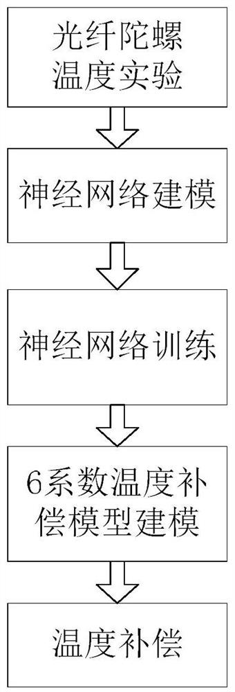
[0041] A step-by-step compensation method for fiber optic gyroscope, please refer to Figure 1-8 , its invention point is, comprises the following steps:

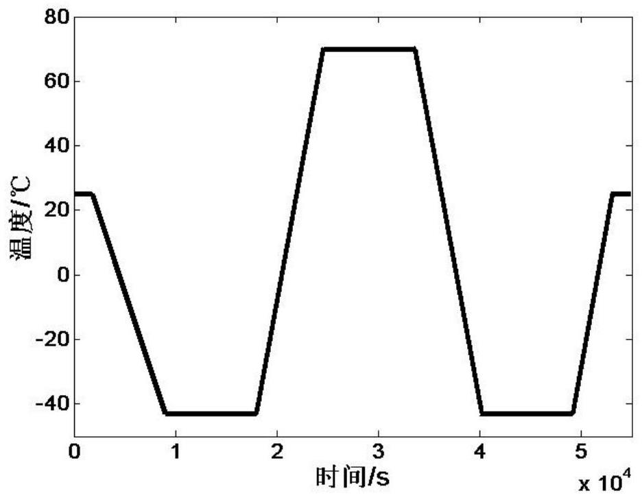
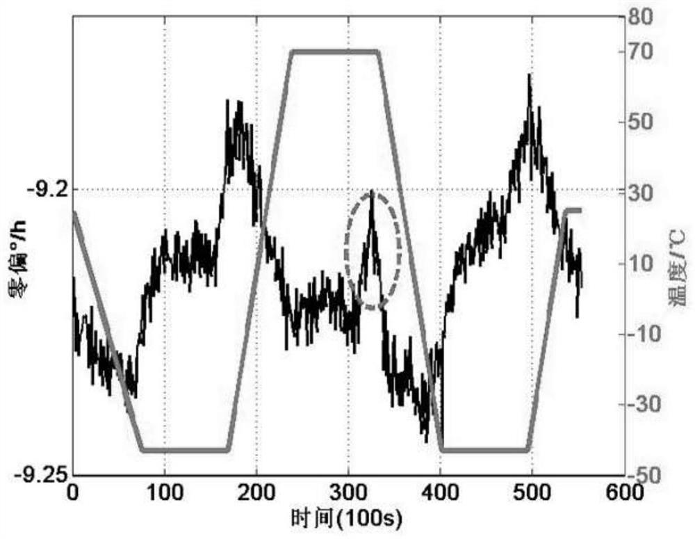
[0042] Step 1. Fiber optic gyroscope temperature experiment

[0043] The normal temperature zero-bias stability of the experimental fiber optic gyroscope is 0.01° / h. The fiber optic gyroscope is placed in a high and low temperature test box with a vibration isolation table for testing. The sensitive axis of the gyroscope points to the sky. The temperature range of the test is -43°C- 70℃, detailed temperature curve as figure 2 shown. The data sampling interval is 1s, and the output angular velocity and temperature values ​​of the gyroscope are collected at the same time, and the length of the sa...


PUM


Abstract

The invention relates to a step-by-step temperature compensation method for a fiber-optic gyroscope, which comprises the following steps of: 1, carrying out temperature test on the fiber-optic gyroscope in a set temperature range, simultaneously collecting the output angular velocity and the temperature value of the gyroscope, and constructing a test temperature curve; 2, establishing a neural network model based on a multi-layer perceptron, wherein the model adopts a three-layer structure and comprises an input layer, a hidden layer and an output layer; 3, training the established neural network model; 4, establishing a polynomial model, wherein the polynomial model adopts a 6-coefficient temperature compensation model; and 5, obtaining a temperature drift compensation value of the fiber-optic gyroscope by utilizing the model in the step 4, and subtracting the temperature drift compensation value of the fiber-optic gyroscope from real-time output data of the fiber-optic gyroscope to finish temperature compensation of the fiber-optic gyroscope. The temperature environment adaptability of the fiber-optic gyroscope is improved by combining the characteristics of high nonlinear fitting precision of the neural network and easy realization of the polynomial model.

Description

technical field [0001] The invention belongs to the technical field of fiber optic gyroscope temperature supplementation, and in particular relates to a step-by-step temperature compensation method for an optical fiber gyroscope. Background technique [0002] Due to its low cost, long life, small size, large dynamic range, wide coverage of precision applications, flexible structural design, simple production process and other advantages, fiber optic gyroscopes are widely used in aviation, aerospace, navigation, weapons, industrial and civil fields, etc. , has a good development prospect and research value. [0003] In practical applications, fiber optic gyroscopes are usually required to have a wide operating temperature range (-40°C ~ +60°C). However, limited by its own characteristics, the error caused by temperature drift has always been the main error source of the fiber optic gyroscope. Therefore, the temperature compensation for fiber optic gyro has been a research h...

Claims


Application Information

Patent Timeline
Patent Type & Authority Applications(China)
IPC IPC(8): G01C25/00G01C19/72G06N3/04G06N3/08
CPCG01C25/005G01C19/72G06N3/04G06N3/08
Inventor 马骏梁鹄李茂春
Owner TIANJIN NAVIGATION INSTR RES INST
Why Eureka
Try Eureka