
A ka-band horizontal end-fire antenna architecture

An end-fire antenna, horizontal technology, applied in the field of Ka-band horizontal end-fire antenna architecture, can solve the problems of low integration, increased height space, cracking, etc., to improve the overall integration, ensure overall performance, and ensure grounding. Effect

Active Publication Date: 2022-04-12
CHENGDU THUNDER MICROCRYSTALLINE TECH CO LTD
View PDF8 Cites 0 Cited by
  • Summary
  • Abstract
  • Description
  • Claims
  • Application Information

AI Technical Summary

Problems solved by technology

[0004] 2. The connection between the antenna and the TR module needs to use the form of SMP-KK-SMP, which needs to increase the height space, about 10mm, and it may be longer according to the length of KK
[0005] 3. Patch antenna, the gain of a single antenna is lower than that of an end-fire antenna, and it meets the requirements of the whole machine in the high frequency band. It is necessary to increase the size of the antenna and the whole machine, which increases the difficulty of antenna design and is not convenient for integrated design.
[0006] The above defects lead to an increase in the height space between the antenna and the TR, low integration, and high difficulty in the process; because the entire structure is in the form of welding, it also leads to poor reworkability; at the same time, the antenna and the SMP core are connected by spot welding. When vibrating, There is a risk of cracking and failure

Method used


Image

  • A ka-band horizontal end-fire antenna architecture
  • A ka-band horizontal end-fire antenna architecture
  • A ka-band horizontal end-fire antenna architecture

Examples


Embodiment

[0040] Aiming at the defects existing in the prior art, this embodiment is optimized and improved to solve the existing technical problems.

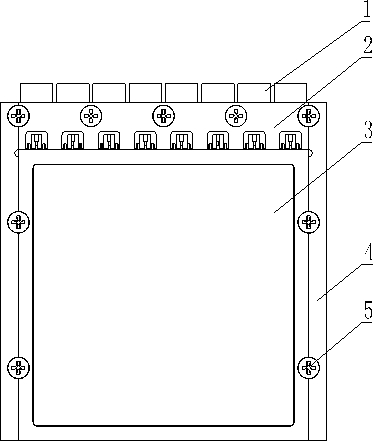
[0041] Specifically, such as Figure 1-Figure 12 As shown, this embodiment discloses a Ka-band horizontal end-fire antenna architecture, referring to image 3 , including a mounting substrate 4, TR modules 3 are connected to both sides of the mounting substrate 4, and several antenna boards 1 are attached to the upper edge of the mounting substrate 4. The antenna boards 1 are connected to the mounting substrate 4 through a pressure plate 2, and the antenna boards 1 and the TR module 3 are connected and communicated through several radio frequency connectors 11; the antenna board 1 and the TR module 3 are both connected to the installation substrate 4 through detachable fasteners 5.

[0042] In the antenna structure disclosed above, the antenna board 1 and the installation substrate 4 are arranged in parallel, which reduces the thickness...


PUM


Abstract

The present invention relates to the technical field of phased array antennas, in particular to a Ka-band horizontal end-fire antenna architecture, which includes a mounting substrate, and TR modules are connected to both sides of the mounting substrate, and several antennas are attached to the upper edge of the mounting substrate The antenna board is provided with a pressure plate, and the antenna board and the TR module are connected and communicated through several radio frequency connectors; the antenna board and the TR module are connected to the installation substrate through detachable fasteners. The structure of the present invention is simple, easy to implement, can reduce the thickness of the antenna structure and the height of the connection, and improve the overall integration of the antenna structure; connect the antenna board and the TR module through the radio frequency connector and connect the two grounds, ensuring The grounding of the antenna structure ensures the overall performance of the antenna structure.

Description

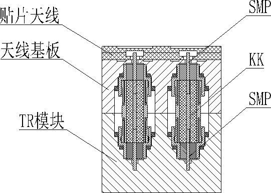
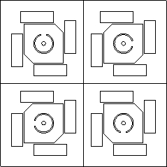
technical field [0001] The invention relates to the technical field of phased array antennas, in particular to a Ka-band horizontal end-fire antenna architecture. Background technique [0002] In the field of phased array antennas, the connection between the antenna and the TR module generally uses the form of SMP-KK-SMP. SMP is sintered on the TR cavity to realize partial airtightness of the TR module. The antenna uses a patch antenna, which is welded on the antenna carrier board for the second time, and SMP is sintered on the antenna carrier board. The specific structure is as follows: figure 1 shown. One of the patch antennas (4) in the form of figure 2 As shown, each SMP is set corresponding to one of the patches. However, there are some defects in the setting form of this patch antenna, as follows: [0003] 1. The form of feed layer + radiation layer is required for antenna design. The antenna needs to be welded three times on the antenna carrier board (the feed la...

Claims


Application Information

Patent Timeline
Patent Type & Authority Patents(China)
IPC IPC(8): H01Q21/06H01Q21/00H01Q1/36H01Q1/50H01Q1/12
CPCH01Q21/061H01Q21/0006H01Q1/50H01Q1/36H01Q1/12
Inventor 伍海林邓金峰张雨豪张开琪万鹏吴凤鼎赵伟叶勇
Owner CHENGDU THUNDER MICROCRYSTALLINE TECH CO LTD
Learn More