
Heat dissipation assembly, compressor and air conditioner

A technology for heat dissipation components and compressors, which is applied to compressors, air conditioning systems, refrigeration components, etc., can solve problems such as overload tripping of fixed-frequency compressor compressors, poor cooling effect of condensers, and air conditioners not working properly, and achieve cost Low cost, stable and reliable heat transfer effect, small footprint effect

Active Publication Date: 2022-02-22
GREE ELECTRIC APPLIANCES INC
View PDF3 Cites 1 Cited by
  • Summary
  • Abstract
  • Description
  • Claims
  • Application Information

AI Technical Summary

Problems solved by technology

When the outdoor ambient temperature is higher, the heat dissipation effect of the condenser is worse, and the heat accumulation will increase the temperature of the compressor body, causing the exhaust temperature to be too high. A kind of protection, so that the air conditioner can not work normally

Method used


Image

  • Heat dissipation assembly, compressor and air conditioner
  • Heat dissipation assembly, compressor and air conditioner
  • Heat dissipation assembly, compressor and air conditioner

Examples


Embodiment 1

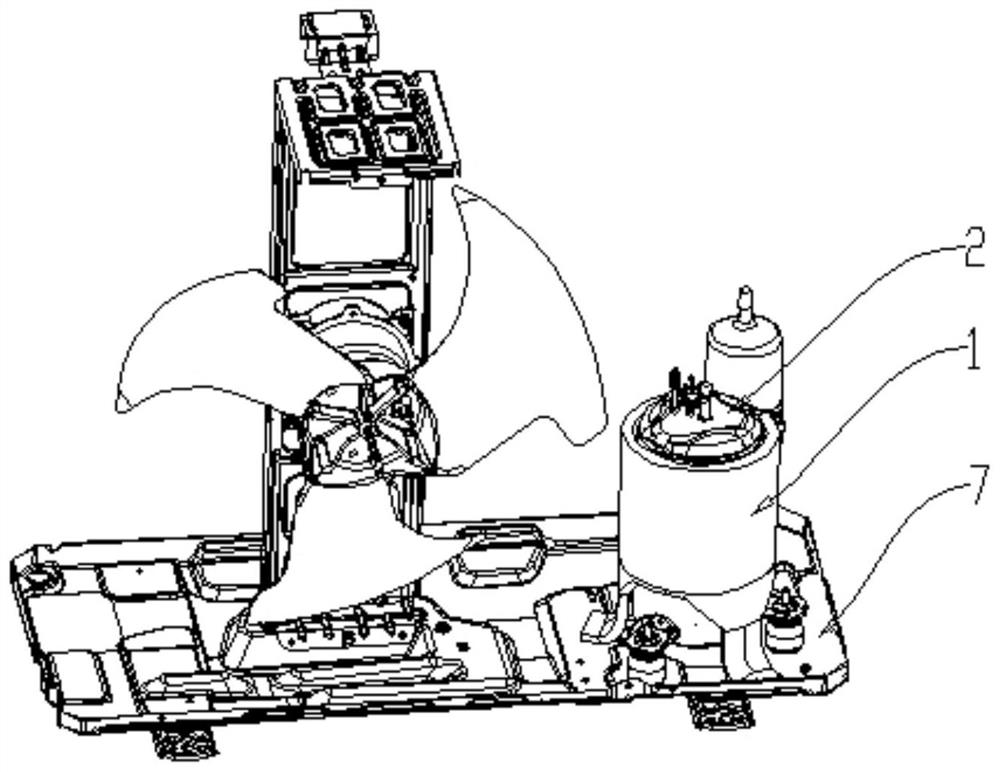
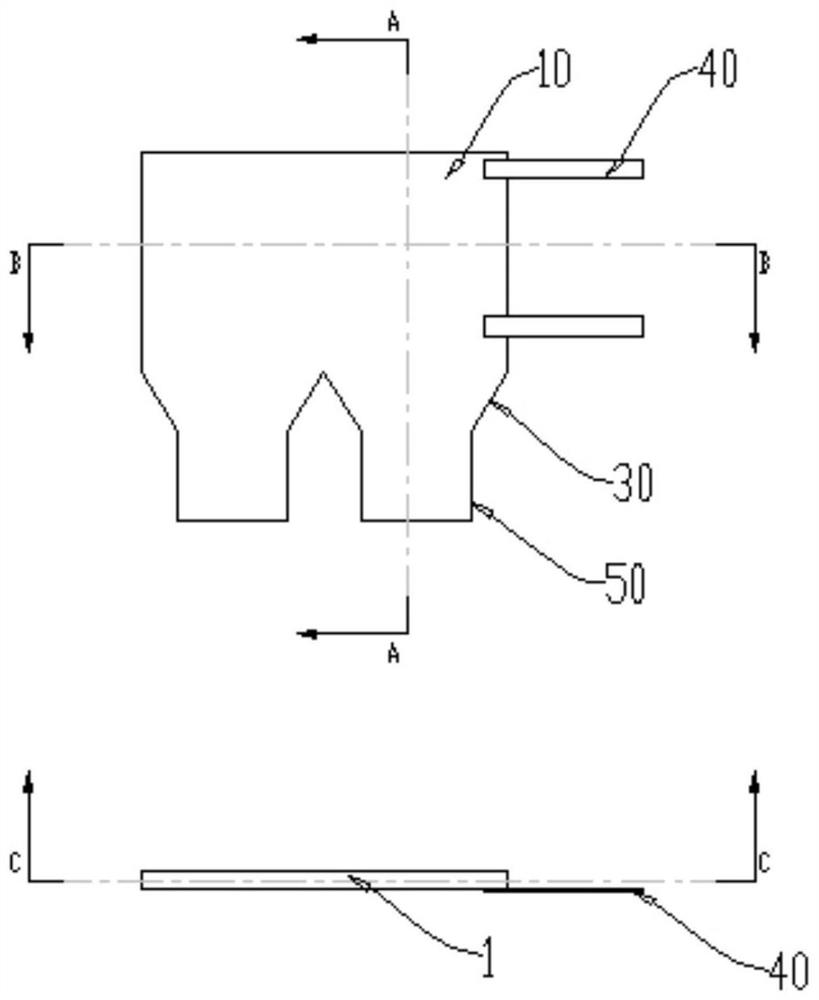
[0037] Such as figure 1 As shown, in view of the fact that the temperature of the cylinder shell is high when the compressor 2 is running, and the chassis 7 has a large area and low temperature, in one embodiment of the present application, a compressor cooling assembly 1 is skillfully proposed. The heat dissipation assembly 1 includes one or more multiple heat dissipation units arranged along the circumference of the compressor 2, and each heat dissipation unit includes:

[0038] The bag body 10, the bag body 10 is used to be arranged on the casing of the compressor 2 to absorb the heat emitted by the compressor 2 casing; the bag body 10 is provided with a first cavity;

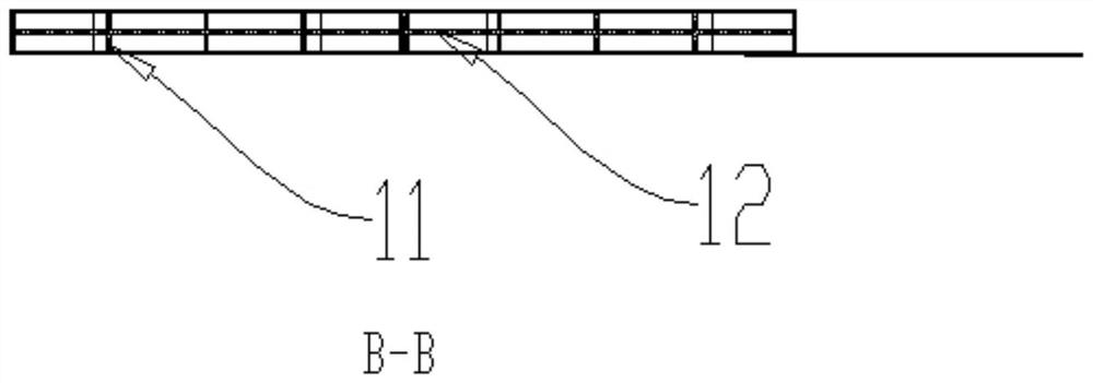
[0039] The middle connecting part 30, the upper end of the middle connecting part 30 is fixedly arranged on the lower end of the bag body 10, the second cavity is arranged in the middle connecting part 30, and the second cavity communicates with the first cavity; the tail part 50, the tail part 50 The upper...

Embodiment 3

[0050] A plurality of heat dissipation units are sequentially connected together along the circumferential direction of the casing to form an annular structure that can be sleeved on the casing of the compressor 2 . The heat dissipation assembly 1 composed of a plurality of heat dissipation units is in contact with the surface of a larger compressor 2 shell, and the heat of the compressor 2 shell is transferred to the heat dissipation assembly 1 to speed up the heat transfer speed.

[0051] Furthermore, a plurality of heat dissipation units are integrally formed or detachably connected together. Multiple heat dissipation units are integrally formed, which can ensure the stability of the overall structure of the heat dissipation unit, play a good supporting role, and reduce the occurrence of cracking due to vibration or thermal expansion and contraction of the compressor 2; multiple heat dissipation units can be detachably connected Together, they can adapt to installation envi...

Embodiment 4

[0054] In one embodiment of the present application, a pump device is disposed in the first cavity of the bag body 10 . Forcing the flow of the heat-conducting liquid to rapidly circulate the heat-conducting liquid among the first cavity, the second cavity and the third cavity can achieve better effects of heat transmission and heat dissipation.


PUM


Abstract

The invention provides a heat dissipation assembly, a compressor and an air conditioner. The heat dissipation assembly comprises one or more heat dissipation units arranged in the circumferential direction of the compressor; each heat dissipation unit comprises a bag body, a middle connecting part and a tail part; the bag body is arranged on a shell body of a compressor shell to absorb heat dissipated by the compressor shell; a first cavity is formed in the bag body; the upper end of the middle connecting part is fixedly arranged at the lower end of the bag body, a second cavity is formed in the middle connecting part, and the second cavity is communicated with the first cavity; and the upper end of the tail part is fixed to the lower end of the middle connecting part, the lower end of the tail part is in heat-conducting connection or contact with a chassis supporting the compressor, a heat transfer process is set in the tail part, spontaneous operation can be achieved, and extra energy consumption is not needed. The heat dissipation assembly has the advantages of no noise, simple structure, small occupied space, low cost, stable and reliable heat transfer effect and no need of subsequent maintenance.

Description

technical field [0001] The invention belongs to the field of air conditioners, and in particular relates to a heat dissipation component, a compressor and an air conditioner. Background technique [0002] Today, it is the compressor that determines the reliable operation of the air conditioner. In order to meet the requirements of preventing rain, rats and insects, the air conditioner compressor is generally placed in the closed cavity of the external unit. The compressor is the main source of noise and vibration of the external unit. In order to reduce its vibration and noise, the compressor is usually mounted on a vibration-damping rubber foot pad, and the outer layer is wrapped with thick sound-proof cotton, which makes it difficult for the heat of the compressor to pass through. Its surface emission is basically absorbed by the refrigerant, and the general condenser exchanges heat with the ambient air and emits it. When the outdoor ambient temperature is higher, the he...

Claims


Application Information

Patent Timeline
Patent Type & Authority Applications(China)
IPC IPC(8): F04B39/06F24F1/08F25B31/00
CPCF04B39/06F24F1/08F25B31/008
Inventor 马超鹏吴小华吴琦李海钦葛小婷
Owner GREE ELECTRIC APPLIANCES INC
Learn More