Stepless speed regulation gearbox for precision drill seeder

A technology of stepless speed regulation and gearbox, which is applied in the field of gearboxes, can solve problems such as high maintenance cost, high production cost, and cumbersome structure, and achieve the effect of reducing maintenance frequency, reducing maintenance cost, and avoiding disassembly and maintenance

Pending Publication Date: 2022-02-22
JILIN KANGDA AGRI MACHINERY
View PDF0 Cites 0 Cited by
  • Summary
  • Abstract
  • Description
  • Claims
  • Application Information

AI Technical Summary

Problems solved by technology

[0003] Most of the traditional adjustable speed reducers are gear set structures, which use cylindrical gears, bevel gears or worms to form a set of transmission mechanisms to achieve the purpose of speed change. Such mechanisms are large in size, heavy in weight and cumbersome in structure. The precision requirement is extremely high, and the production cost is high. On the basis of the reduction gear set, the traditional adjustable speed reducer uses the crankshaft, shift fork, planetary gear and other parts to achieve the purpose of speed regulation, which also leads to the traditional adjustable speed reducer. Reducer manufacturing difficulties, frequent maintenance cycles, high maintenance costs and other disadvantages

Method used


Image

  • Stepless speed regulation gearbox for precision drill seeder
  • Stepless speed regulation gearbox for precision drill seeder
  • Stepless speed regulation gearbox for precision drill seeder

Examples


Embodiment

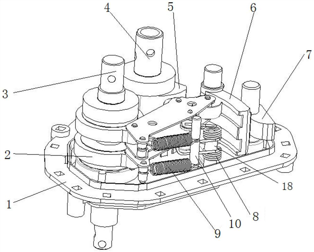
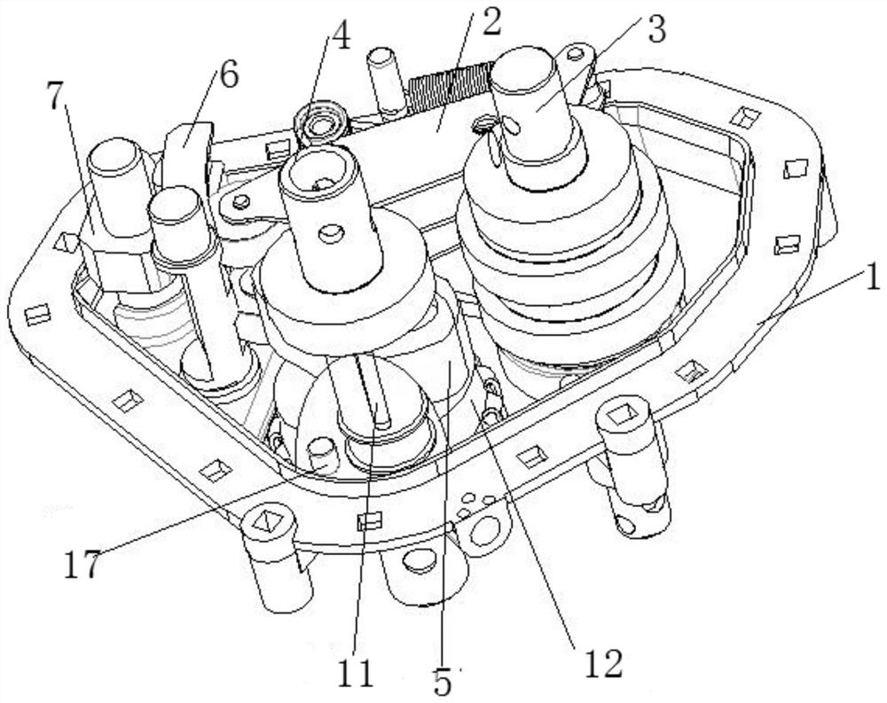
[0043] figure 1 It shows a schematic diagram of a continuously variable speed transmission with the upper casing removed according to an embodiment of the present invention; figure 2 It shows a schematic diagram of another direction of the continuously variable speed-variable gearbox without the upper casing according to an embodiment of the present invention.

[0044] Such as figure 1 and figure 2 As shown, this embodiment proposes a stepless speed-adjustable gearbox for a precision seed drill, including an upper casing 13 and a lower casing 1, and an output between the lower casing 1 and the upper casing 13 The shaft 3 and the input shaft 4, the input shaft 4 is provided with a first keyway, the lower housing 1 is provided with a shaft sleeve, and the continuously variable speed gearbox also includes:

[0045] The curved plate assembly includes a curved plate shaft and a curved plate 6 that is sheathed on the crank plate shaft. The curved plate assembly is arranged on t...


PUM


Abstract

The invention provides a stepless speed regulation gearbox for a precision drill planter, wherein the stepless speed regulation gearbox comprises an upper shell, a lower shell, an output shaft and an input shaft, and further comprises a bent plate assembly, the bent plate assembly comprises a bent plate shaft and a bent plate, the bent plate assembly is arranged on the lower shell through the bent plate shaft, and the bent plate is provided with a bent plate groove; a bent plate limiting block is movably arranged on the lower shell and located on the side opposite to the bent plate groove; a cam is arranged on the input shaft; the roller assembly comprises a pair of positioning plates arranged in parallel, a one-way bearing and rollers, the rollers comprise a first roller and a second roller, the one-way bearing is arranged on the output shaft and connected with the pair of positioning plates through a one-way bearing seat, the first roller is arranged in the bent plate groove, and the second roller makes contact with the cam; a spring pull rod is arranged on a shaft sleeve of the lower shell and located between a reset spring positioning shaft and the bent plate assembly; and a reset spring is arranged between the reset spring positioning shaft and the spring pull rod. The structure is simple, the mechanical performance is stable, the size is light, and frequent disassembly for maintenance is avoided.

Description

technical field [0001] The invention relates to the technical field of gearboxes, in particular to a stepless speed-adjusting gearbox for precision drills. Background technique [0002] Continuously variable transmission refers to a transmission system that can continuously obtain any transmission ratio within the transmission range. [0003] Most of the traditional adjustable speed reducers are gear set structures, which use cylindrical gears, bevel gears or worms to form a set of transmission mechanisms to achieve the purpose of speed change. Such mechanisms are large in size, heavy in weight and cumbersome in structure. The precision requirement is extremely high, and the production cost is high. On the basis of the reduction gear set, the traditional adjustable speed reducer uses the crankshaft, shift fork, planetary gear and other parts to achieve the purpose of speed regulation, which also leads to the traditional adjustable speed reducer. The reducer is difficult to ...

Claims


Application Information

Patent Timeline
Patent Type & Authority Applications(China)
IPC IPC(8): F16H25/10F16H57/02F16H57/029
CPCF16H25/10F16H57/02F16H57/029
Inventor 刘丽娜陈丽敏王智超张男梁波
Owner JILIN KANGDA AGRI MACHINERY
Why Eureka
Try Eureka