
Method for scratching battery piece by using laser and device thereof

A battery sheet and laser technology, applied in laser welding equipment, circuits, electrical components, etc., can solve problems affecting the power generation efficiency and aesthetics of battery strings and components, and achieve the effect of changing the path of lobes

Pending Publication Date: 2022-02-25
NINGXIA XN AUTOMATION EQUIP CO LTD
View PDF2 Cites 0 Cited by
  • Summary
  • Abstract
  • Description
  • Claims
  • Application Information

AI Technical Summary

Problems solved by technology

The core technology of the laminated module technology is the slicing technology of the solar cell. The current slicing technology of the solar cell uses a laser to cut a crack on the surface of the cell, and then mechanically breaks the solar cell. The slices are separated; two lasers are also used, the first laser is used to draw the split line of the cell, the other laser heats the split line of the cell, and at the same time sprays a cooling medium to the split line to split the cell, such as The invention patent application with the patent publication number CN111151896A discloses a cutting method and cutting equipment for solar cells, and the patent application with the patent publication number CN111916532A discloses a method and device for efficiently splitting solar cells. In the process of the slicing method disclosed in the above-mentioned patent, it was found that when the laser beam acting on the battery sliced ​​the battery slice along a straight line, the cracking line of the battery slice had a certain arc, and when the laser beam sliced ​​the battery of the same material When the cell is cut, the radian direction of the cracking line of the cell is the same, and the offset range of the arc is between 100 and 200 μm. After the cell is cut and split, the width of each segment becomes narrower or wider. After the battery strings are interconnected, the cell spacing in the width direction of the cells is relatively small. Therefore, the power generation efficiency and aesthetics of the battery strings and components will be affected after the segments with curved edges are welded into battery strings and packaged into modules.

Method used


Image

  • Method for scratching battery piece by using laser and device thereof
  • Method for scratching battery piece by using laser and device thereof
  • Method for scratching battery piece by using laser and device thereof

Examples


Embodiment Construction

[0032] Combine below Figure 1 to Figure 8 Specific embodiments of the present invention will be described.

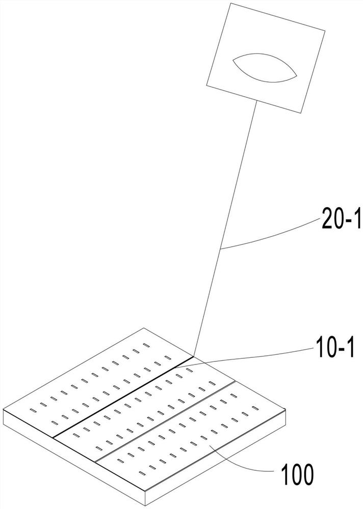
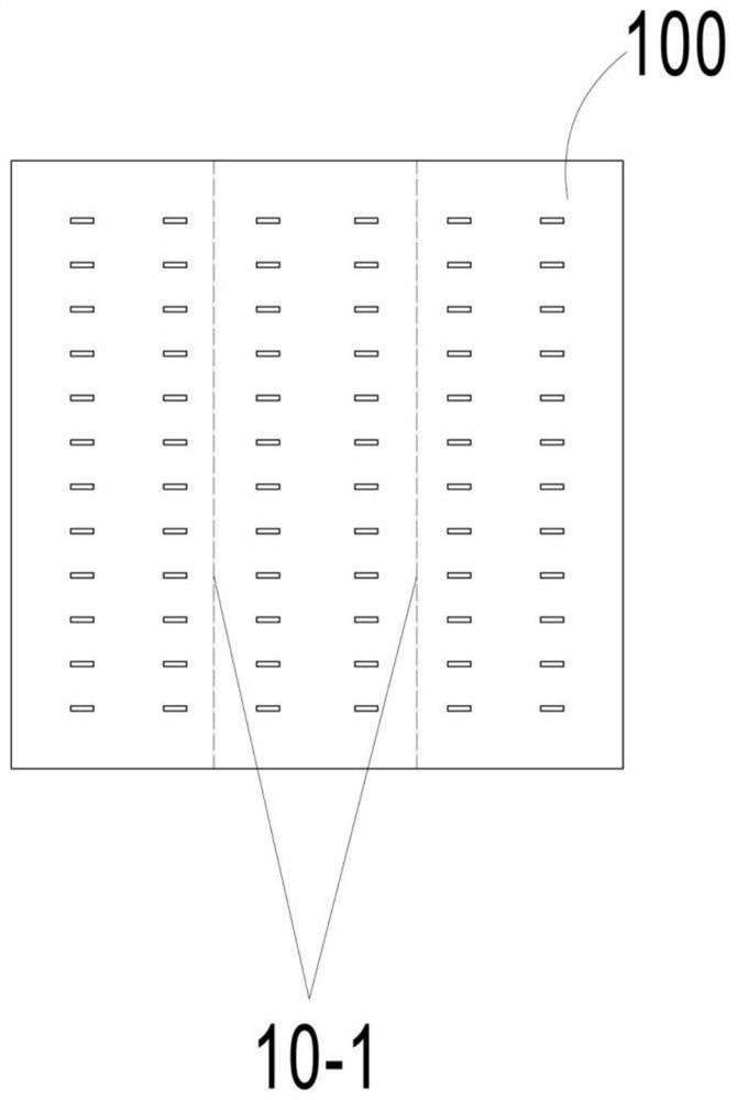
[0033] figure 1 and figure 2 The scene where the laser beam acts on the cell is shown in three slices. The ideal split line 10-1 is on the plane of the cell 100 and perpendicular to the direction of the grid line of the cell 100, dividing the cell 100 into N equal parts, where N is a natural number greater than or equal to 2;

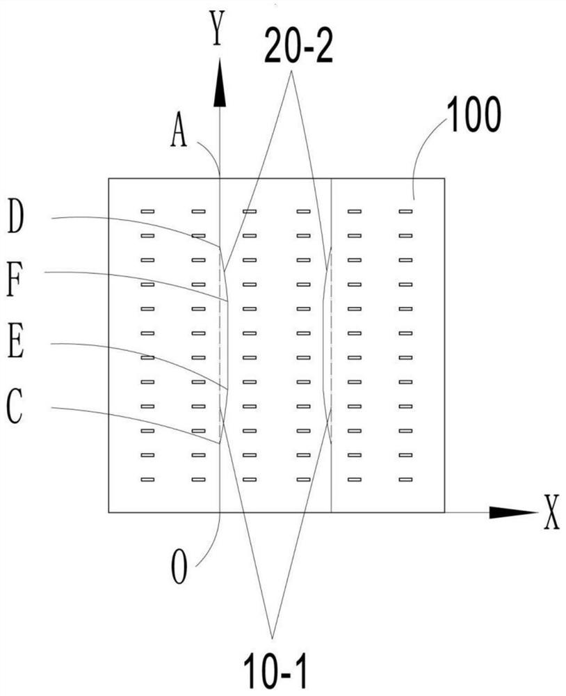
[0034] image 3 It shows that one of the endpoints of any ideal splitting line is taken as the origin, and a coordinate system is established on the plane where the battery sheet 100 is located, with the focus of the laser beam 20-1 at the starting point O of the ideal splitting line 10-1 as the origin, and point O The line connecting point A is the y-axis, and the line passing through the origin and parallel to the grid line of the battery sheet 100 is the x-axis. The trajectory 20-2 is the focus of the laser beam 20-1 on the XY coordinate...


PUM


Abstract

The invention relates to a method for scratching a battery piece by using laser and a device thereof, scratching is carried out on the battery piece according to the pre-designed track line, slicing cutting of the battery piece is achieved, the situation that the deviation of a splitting line is large after the battery piece is cut is avoided, and the design of the track line needs to refer to the shape of the battery piece deformation splitting line in the prior art; and therefore, the purpose of rectifying and cutting the battery piece is achieved.

Description

technical field [0001] The invention relates to a method of using a laser to scratch a cell, in particular to a method for using a laser to scratch a cell. Background technique [0002] In recent years, the vigorous promotion and application of laminated module technology has led to the rapid development of solar cell splitting technology. [0003] Due to the higher performance of laminated components, various component manufacturers have begun to produce such laminated components. The core technology of the laminated module technology is the slicing technology of the solar cell. The current slicing technology of the solar cell uses a laser to cut a crack on the surface of the cell, and then mechanically breaks the solar cell. The slices are separated; two lasers are also used, the first laser is used to draw the split line of the cell, the other laser heats the split line of the cell, and at the same time sprays a cooling medium to the split line to split the cell, such as...

Claims


Application Information

Patent Timeline
IPC IPC(8): B23K26/362B23K26/00H01L21/78H01L31/18
CPCB23K26/362B23K26/00H01L21/78H01L31/18Y02P70/50
Inventor 杨勇雍刚王小牛陈世庚
Owner NINGXIA XN AUTOMATION EQUIP CO LTD
Learn More