
Method for marking adjacent astrocytes

A technology for labeling astrocytes, applied in the field of biomedicine, can solve problems such as difficult promotion and use, low efficiency of dual fluorescent labeling, and high technical difficulty, and achieve improved labeling efficiency, strong proliferation and migration capabilities, and low technical difficulty Effect

Active Publication Date: 2022-02-25
WEST CHINA HOSPITAL SICHUAN UNIV
View PDF13 Cites 0 Cited by
  • Summary
  • Abstract
  • Description
  • Claims
  • Application Information

AI Technical Summary

Problems solved by technology

[0005] The first object of the present invention is to provide a method for labeling adjacent astrocytes, which is used to solve the problems of low efficiency of double fluorescent labeling in the prior art, high technical difficulty, and difficult promotion and use

Method used


Image

  • Method for marking adjacent astrocytes
  • Method for marking adjacent astrocytes
  • Method for marking adjacent astrocytes

Examples


Embodiment 1

[0037] Plasmid construction and viral packaging.

[0038] Backbone plasmid: pAAV2-GfaABC1D-mRuby3-WPRE-pA (Shanghai Taiertu Biotechnology Co., Ltd., No. S0790-P), in which the GfaABC1D promoter is the human glial-derived acidic protein promoter, that is, the astrocyte-specific promoter ; mRuby3 is a red fluorescent protein; WPRE is a post-transcriptional regulatory element, which can enhance the expression of the target gene; pA is a poly A tail, which can enhance the stability of the target gene in cells.

[0039] Plasmid construction: Digest the backbone plasmid with BamHI and NotI: pAAV2-GfaABC1D-mRuby3-WPRE-pA (No. S0790-P), recover the linearized vector, and use the S0254-P (pAAV2-CAG-EBFP-WPRE-pA) plasmid As a template, the EBFP sequence fragment was amplified, and the EBFP sequence was seamlessly cloned into a linear vector to construct the pAAV2-GfaABC1D-EBFP-WPRE-pA plasmid. Using the same method, use pAAV2-hSyn-EGFP-WPRE-pA (No. S0237-P) as a template to amplify the...

experiment example 1

[0046] Astrocytes were labeled in the manner of Example 1, and obtained as follows Figure 4 image shown.

[0047] like Figure 4 As shown, there are labeled astrocytes on the coronal brain slice of the mouse, among which there are a large number of EBFP (purple), EGFP (green) and EBFP / EGFP double positive (white) labels in the cortex, thalamus and hypothalamus Star glue, in Figure 4 The white arrows in indicate the adjacent astrocytes labeled with EBFP and EGFP, respectively, indicating that the method of Example 1 can effectively label the adjacent astrocytes.

Embodiment 2

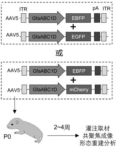
[0049] This example uses the same experimental method as Example 1, the difference is that the fluorescent protein combination used in this example is EGFP and mCherry, because mCherry has high photostability, but it is easy to aggregate, which is not conducive to the display of astrocytes Therefore, it is rarely used in the prior art for labeling astrocytes. In this example, AAV5-GfaABC1D-EGFP and AAV5-GfaABC1D-mCherry through plasmid construction and virus packaging Dilute to 2~5×10 11 vg / mL, mixed at a volume ratio of 2:1 and combined for injection.


PUM

PropertyMeasurementUnit
The inside diameter ofaaaaaaaaaa
Lengthaaaaaaaaaa

Abstract

The invention relates to the field of biological medicines, in particular to a method for marking adjacent astrocytes, which is used for solving the problems of low efficiency, high technical difficulty and difficulty in popularization and application of dual fluorescence marking in the prior art, and can further realize multiple fluorescence marking. The method mainly comprises the steps of plasmid construction, virus packaging, virus injection and image acquisition, in the plasmid construction step, different fluorescent proteins are inoculated into skeleton plasmids, then plasmids containing target genes and pHelper plasmids of AAV5 are co-transfected into a human embryo kidney cell line (AAV-293) to complete virus packaging, during virus injection, P0 or P1 wild type mice are adopted, after the virus is expressed for 2-4 weeks, operations such as perfusion sampling and the like are carried out, so that a multi-brain region is reached, and the marking of adjacent astrocytes is efficiently completed.

Description

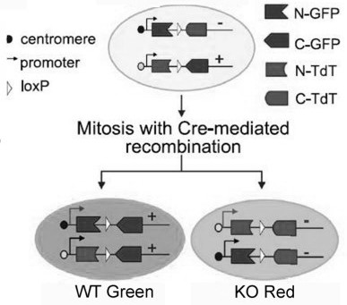
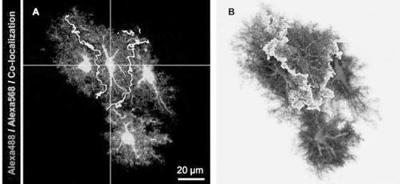
technical field [0001] The invention relates to the technical field of biomedicine, in particular to a method for labeling adjacent astrocytes. Background technique [0002] Astrocytes (astrocytes) are widely distributed in the central nervous system of mammals, and have a multi-level, sponge-like complex shape. The fine branches of astrocytes can communicate with adjacent neurons, oligodendrocytes and Blood vessels, etc. are in contact with each other, and then participate in the regulation of brain function. The fine branches of adjacent astrocytes can also contact each other, and exchange materials and signals between cells through gap links. Bushong, E.A et al. reported that in CA1 of the hippocampus, adjacent astrocytes have independent, non-overlapping spatial domains, such as figure 1 As shown, a number of subsequent studies also reported similar phenomena in the central nervous system of humans and Drosophila, suggesting evolutionary conservation. Since then, this ...

Claims


Application Information

Patent Timeline
IPC IPC(8): C12N5/10C12N15/864C12N15/65
CPCC12N5/0622C12N15/86C12N15/65C12N2750/14143C12N2510/00C12N2800/107Y02A50/30
Inventor 周斌
Owner WEST CHINA HOSPITAL SICHUAN UNIV
Learn More