Magnetic field measurement method of single-beam light turn-back pumping detection configuration and atomic magnetometer

A technology for pump detection and magnetic field measurement, which is applied in the use of magneto-optical equipment for magnetic field measurement, magnetic field size/direction, etc. question

Active Publication Date: 2022-02-25
SOUTH UNIVERSITY OF SCIENCE AND TECHNOLOGY OF CHINA
View PDF8 Cites 0 Cited by
  • Summary
  • Abstract
  • Description
  • Claims
  • Application Information

AI Technical Summary

Problems solved by technology

[0005] In view of the deficiencies in the prior art above, the object of the present invention is to provide a magnetic field measurement method and an atomic magnetometer system of a single-beam light reentrant pump detection configuration. Adjustment to generate strong pump light and weak probe light in turn can ensure a compact and miniaturized magnetometer under the premise of high sensitivity, so as to realize the array of atomic magnetometer probes and approach the magnetic field source to be measured, and solve the problem of In the prior art, two laser beams are input to detect the magnetic field at the same time, which leads to the complexity of the optical path of the whole system, which is not conducive to the miniaturization and array design of the atomic magnetometer, and reduces its applicability.

Method used


Image

  • Magnetic field measurement method of single-beam light turn-back pumping detection configuration and atomic magnetometer
  • Magnetic field measurement method of single-beam light turn-back pumping detection configuration and atomic magnetometer
  • Magnetic field measurement method of single-beam light turn-back pumping detection configuration and atomic magnetometer

Examples


Embodiment Construction

[0060] The present invention provides a magnetic field measurement method and an atomic magnetometer in a single-beam light return pump detection configuration. In order to make the purpose, technical solution and effect of the present invention clearer and clearer, the present invention will be further described in detail below with reference to the accompanying drawings and examples. It should be understood that the specific embodiments described here are only used to explain the present invention, not to limit the present invention.

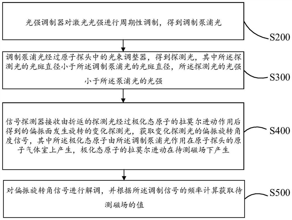
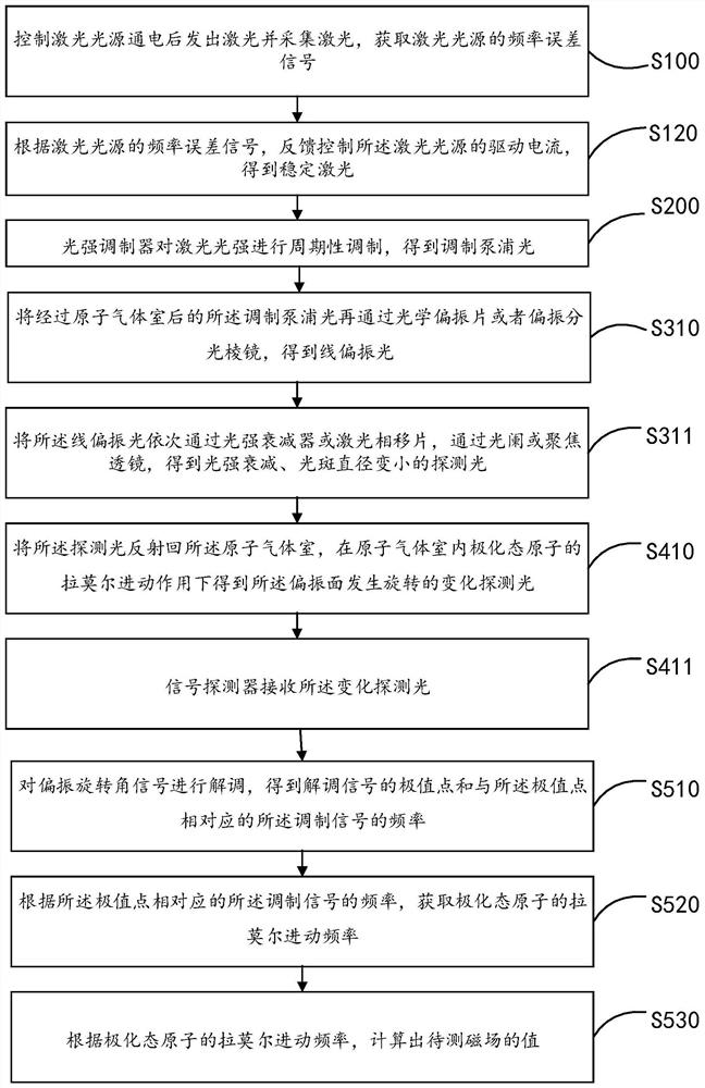
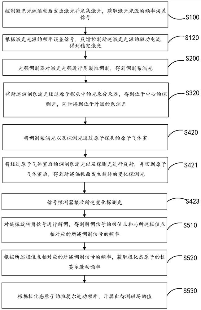
[0061] The basic working principle of the all-optical atomic magnetometer is as follows: First, a beam of laser light is irradiated on the alkali metal atomic gas, and the atoms are pumped, so that the atoms are redistributed on the magnon energy level, and the macroscopic appearance is atomic With a certain polarization orientation, this process is the preparation process of the polarized state of the atom; then the polarized atoms will underg...


PUM


Abstract

The invention discloses a magnetic field measurement method of a single-beam light turn-back pumping detection configuration and an atomic magnetometer. The method comprises the steps: carrying out periodic modulation on light intensity of laser through a light intensity modulator to obtain modulated pump light; enabling the modulated pump light to pass through a light beam regulator in an atomic probe to obtain detection light; enabling a signal detector to receive changed detection light with a polarization plane rotating, wherein the changed detection light is obtained after the returned detection light passes through a Larmor precession action of a polarization state atom; obtaining a polarization rotation angle signal, wherein the polarization state atom is generated by the modulated pump light acting on the atom gas chamber of the atom probe, and the larmor precession of the polarization state atom is generated under the to-be-measured magnetic field; and demodulating the polarization rotation angle signal, and calculating according to the frequency of the modulation signal to obtain the value of the to-be-measured magnetic field. According to the invention, the problems that in the prior art, two laser beams are input to detect the magnetic field, so that the light path of the whole system is complex, miniaturization and array design of the atomic magnetometer is not facilitated, and the applicability of the atomic magnetometer is reduced are solved.

Description

technical field [0001] The invention relates to the field of magnetic field measurement, in particular to a magnetic field measurement method of a single-beam light return pump detection configuration and an atomic magnetometer. Background technique [0002] Magnetic field detection has a wide range of needs in the fields of resource exploration, geophysics, nondestructive testing, biomedicine, national defense and basic science. For example: in the field of defense industry for anti-submarine, navigation, resource exploration, non-destructive testing, etc.; in the field of biomedicine for magnetic imaging of the heart, brain and other organs, providing new imaging methods for medical diagnosis; in basic discipline research In the field, it is used to find the permanent electric dipole moment in neutral particles, check the basic symmetry, etc. At present, the most sensitive commercial magnetometer is superconducting quantum interference magnetometer. With the development o...

Claims


Application Information

Patent Timeline
Patent Type & Authority Applications(China)
IPC IPC(8): G01R33/032
CPCG01R33/032
Inventor 张卫东徐晓天杨胜军范靖云
Owner SOUTH UNIVERSITY OF SCIENCE AND TECHNOLOGY OF CHINA
Why Eureka
Try Eureka