Power amplifier and radio frequency chip

A power amplifier and emitter technology, applied in power amplifiers, amplifier types, high-frequency amplifiers, etc., can solve problems such as inability to adjust, inability to achieve linear and continuous adjustment of gain, and inability to adjust gain linearly enough to achieve good results and achieve Feedback can be adjusted linearly and continuously

Active Publication Date: 2022-02-25
LANSUS TECH INC
View PDF7 Cites 1 Cited by
  • Summary
  • Abstract
  • Description
  • Claims
  • Application Information

AI Technical Summary

Problems solved by technology

It can be concluded that the gain of the power amplifier in the related art can only exist in two ways, high and low, and the gain of the middle gear cannot be adjusted.
The power amplifier in the related art adjusts its gain by adding some feedback control, but the adjustment of the gain by these feedback controls is not linear enough.
Cannot achieve linear and continuous adjustment of gain

Method used


Image

  • Power amplifier and radio frequency chip
  • Power amplifier and radio frequency chip
  • Power amplifier and radio frequency chip

Examples


Embodiment Construction

[0035] Specific embodiments of the present invention will be described in detail below in conjunction with the accompanying drawings.

[0036] The specific implementations / examples described here are specific specific implementations of the present invention, and are used to illustrate the concept of the present invention. limit. In addition to the embodiments described here, those skilled in the art can also adopt other obvious technical solutions based on the claims of the application and the contents disclosed in the description, and these technical solutions include adopting any obvious changes made to the embodiments described here. The replacement and modified technical solutions are all within the protection scope of the present invention.

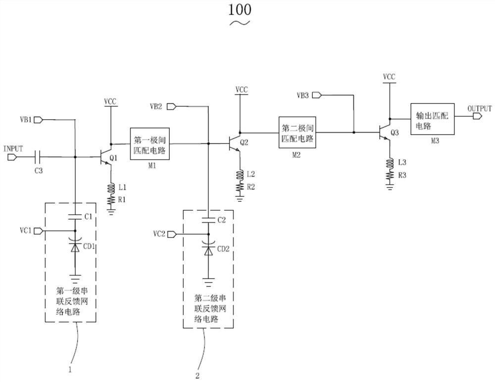
[0037] The present invention provides a power amplifier 100 . Please also refer to image 3 as shown, image 3 It is a circuit structure diagram of the power amplifier of the embodiment of the present invention.

[0038] The powe...


PUM


Abstract

The invention provides a power amplifier. The power amplifier comprises a third capacitor, a first transistor, a first-stage matching circuit, a second transistor, a second-stage matching circuit, a third transistor, an output matching circuit, a first-stage series feedback network circuit bridged between a base electrode of the first transistor and the ground, and a second-stage series feedback network circuit bridged between a base electrode of the second transistor and the ground. The first-stage series feedback network circuit is used for adjusting the circuit equivalent capacitance value of the first-stage series feedback network circuit according to the first control voltage so as to adjust the gain of the first transistor. The second-stage series feedback network circuit is used for adjusting the circuit equivalent capacitance value of the second-stage series feedback network circuit according to the second control voltage so as to adjust the gain of the second transistor. The invention also provides a radio frequency chip. By the adoption of the technical scheme, the gain of the power amplifier can be linearly and continuously adjusted, and the effect of restraining low frequency and high frequency outside the working frequency band is good.

Description

technical field [0001] The invention relates to the field of amplifier circuits, in particular to a power amplifier and a radio frequency chip. Background technique [0002] At present, in the wireless transceiver system, the radio frequency power amplifier is one of the important components. The power amplifier amplifies the power of the signal. After obtaining sufficient radio frequency power, the signal can be fed to the antenna for radiation. Among them, the gain of the power amplifier is an important performance index. [0003] A power amplifier in the related art includes a DC blocking capacitor, a first transistor, a first-stage matching circuit, a second transistor, a second-stage matching circuit, a third transistor, and an output matching circuit connected in sequence. Among them, such as figure 1 The power amplifier shown is a commonly used power amplifier in the related art. The power amplifier is a typical three-stage power amplifier. Wherein, the power ampl...

Claims


Application Information

Patent Timeline
Patent Type & Authority Applications(China)
IPC IPC(8): H03F1/34H03F3/21H03F3/19H03G3/30
CPCH03F1/34H03F3/21H03F3/19H03G3/3042H03F2200/451
Inventor 周佳辉郭嘉帅
Owner LANSUS TECH INC
Why Eureka
Try Eureka