
Oriented fiber reinforced cementing connection method

A fiber-reinforced and connecting method technology, which is applied in the field of composite parts connection, can solve the problems of long repair cycle, change of part structure and shape, and large workload, so as to reduce the difficulty of operation, reduce the weight of parts, and improve the overall rigidity.

Active Publication Date: 2022-03-01
HARBIN
View PDF5 Cites 0 Cited by
  • Summary
  • Abstract
  • Description
  • Claims
  • Application Information

AI Technical Summary

Problems solved by technology

This kind of repair method has a long repair period and high repair cost. It needs to use heating equipment and molds. The workload is large and the process is complicated. There is a greater risk, the strength recovery after repair is not ideal, and there are certain changes in the structural shape of the parts
For some modifications, mechanical connection methods such as riveting are often used for modification, which requires giving up some aerodynamic performance, adding reinforcement plates on the surface of the parts and drilling and riveting. This type of modification is an irreversible modification, once the modification is completed. Difficult to restore
In addition, this type of modification method needs to destroy the original structure, such as drilling, etc., which makes the test results deviate to a certain extent.

Method used


Image

  • Oriented fiber reinforced cementing connection method
  • Oriented fiber reinforced cementing connection method
  • Oriented fiber reinforced cementing connection method

Examples


Embodiment Construction

[0042] The present application will be further described in detail below through specific implementation modes in conjunction with the accompanying drawings.

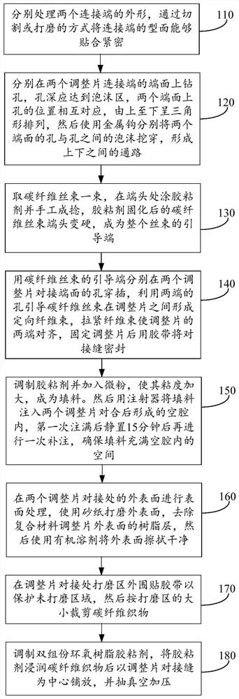
[0043] See figure 1 , which is a flowchart of a directional fiber-reinforced adhesive connection method provided by the present invention, comprising the following steps:

[0044] Step 110 , processing the shapes of the two connecting ends separately, and making the profiles of the connecting ends closely fit by cutting or grinding.

[0045] The profiles of the connecting ends can be fitted tightly by cutting or grinding to ensure that the gap between the joints is not greater than 2mm.

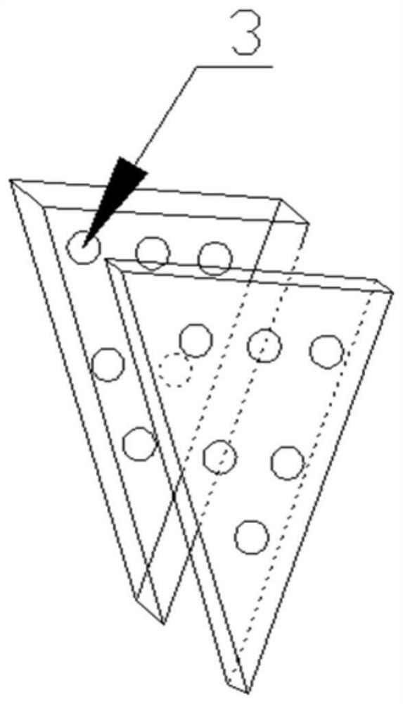
[0046] Step 120. Drill holes on the end faces of the connecting ends of the two adjustment pieces respectively. The depth of the holes should reach the foam area. The positions of the holes on the two end faces correspond to each other and are arranged in a triangle from top to bottom. The foam between the holes is dug through to for...


PUM


Abstract

The invention provides a directional fiber reinforced glue joint connection method, and belongs to the technical field of composite material part connection. Drilling holes in the end surfaces of the connecting ends of the two adjusting sheets; the ends of the carbon fiber filaments are coated with an adhesive; inserting carbon fiber tow guide ends into the holes in the butt joint end faces of the two adjusting sheets, guiding the carbon fiber tow to form a directional fiber bundle between the adjusting sheets through the holes in the two ends, and tensioning the fiber bundle to enable the two ends of the adjusting sheets to be aligned; filling the filler into a cavity formed after the two adjusting sheets are folded, removing the adhesive tapes on the adjusting sheets after the filler is cured, and performing surface treatment on the outer surfaces of the butted parts of the adjusting sheets; cutting the carbon fiber fabric according to the size of the polishing area; and preparing a two-component epoxy resin adhesive, infiltrating the carbon fiber fabric with the adhesive, and laying the carbon fiber fabric by taking the butt seam of the adjustment sheet as the center. And the strength of a connected composite material structural part can be effectively guaranteed, changes of structural attributes are reduced, the manufacturing cost is low, implementation is convenient, and the method is used for connecting composite material parts.

Description

technical field [0001] The application belongs to the technical field of composite material part connection, and in particular relates to a directional fiber-reinforced adhesive connection method. Background technique [0002] During the development stage of aircraft, a large number of structural parts are required for mechanical performance tests. Among them, composite structural parts need a large number of verification tests to ensure that their structural performance meets the expected goals. Typical structural parts of composite materials with cavity structures, such as rudder surface structures and trim pieces in the wing and tail systems of fixed-wing aircraft, have the characteristics of multiple cavities. The length, size, and angle of this type of product structure all affect the aerodynamic performance of the rudder surface, especially the size of the control force of the rudder surface during the flight of the aircraft. In the process of aircraft development, it...

Claims


Application Information

Patent Timeline
IPC IPC(8): B29C70/68B29C70/84B29C73/24
CPCB29C70/683B29C70/845B29C70/681B29C73/24
Inventor 张超刘永光张馨予祁书涛
Owner HARBIN
Learn More