
Patsnap Eureka
For R&D, Patsnap Eureka makes reading and utilizing patents & technical documents easy.
Patsnap Eureka AIR
Designed for self-driven R&D workflows. Generate viable solutions, solve complex R&D challenges, empower your innovation with AI.

Patsnap Eureka Materials
Designed for material experts only. Revolutionize your material R&D, from search, analyze, to developing new materials.

TechResearch
Generate reliable direction feasibility study reports for your R&D in just a few steps.

TechSeek
Discover and master advanced knowledge NOW. Basics, ideas, possibilities, all at once.

TechMind
As an expert in R&D Theories, TechMind can generates customized viable solutions instantly.

TechRisk
Analyze your overall solution with one click, know your potential R&D risks in advance.

TechMonitor
Get weekly tech updates, stay abreast of the latest tech innovations and key insights.
Optical glass smelting furnace
A technology of optical glass and melting furnace, which is applied in glass furnace equipment, glass manufacturing equipment, furnaces, etc., can solve the problems of long glass melting time, lower glass melting efficiency, and large volume of waste glass, so as to reduce risk, increase speed, The effect of improving quality
- Summary
- Abstract
- Description
- Claims
- Application Information
AI Technical Summary
Problems solved by technology
Method used
Image

Examples
specific Embodiment approach
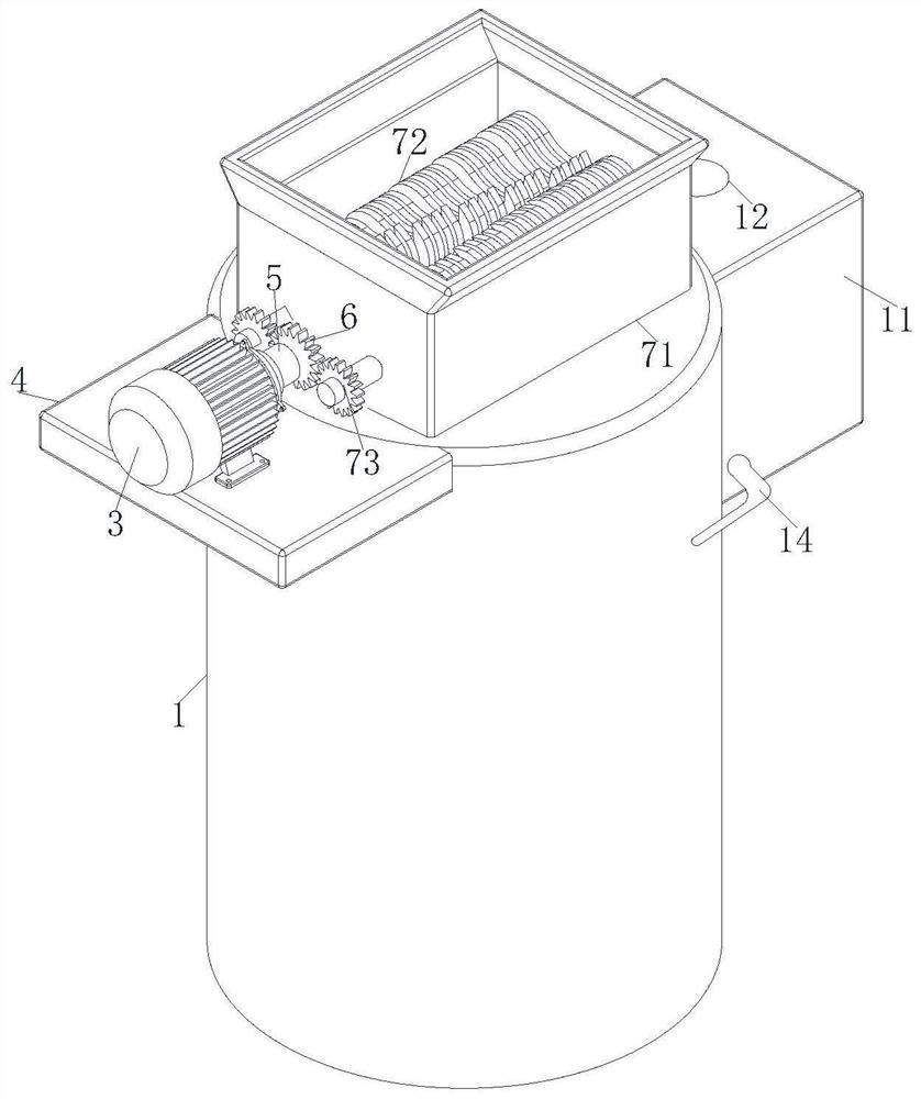
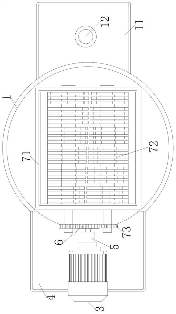
[0052] As a specific embodiment of the present invention, the crushing assembly 8 includes:
[0053] A feed hopper 81; the feed hopper 81 is fixed on the top of the furnace body 1;
[0054]Crushing wheel 82; the crushing wheel 82 is arranged in the feed hopper 81, the rotating shaft of the crushing wheel 82 runs through the feeding hopper 81 near the motor 4 side, and the end of the crushing wheel 82 rotating shaft close to the motor 4 is fixedly connected to the driven Gear 83; the driven gear 83 is meshed with the driving gear 6;
[0055] Dropping board 84, said dropping board 84 is fixedly connected to the inner wall of furnace body 1, and is used for concentrating and falling the crushed glass into furnace body 1;
[0056] After the staff starts the motor 4, the driving gear 6 at the output end of the motor 4 rotates. During the rotation of the driving gear 6, it drives the driven gear 83 to rotate, causing the crushing wheel 82 to rotate in reverse; The glass blocks are...
Embodiment approach
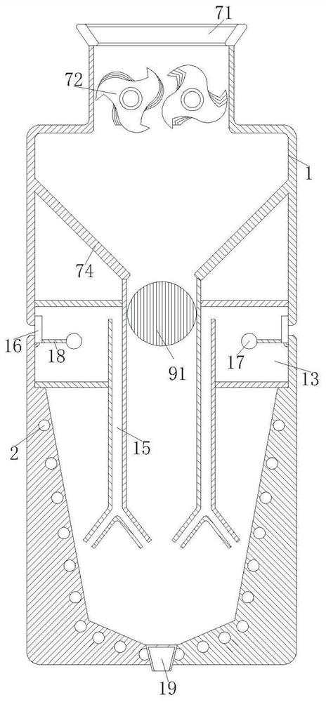
[0073] As a specific embodiment of the present invention, the diameter of the liquid inlet pipe 12 close to the top of the water tank 11 is larger than the diameter of the liquid inlet pipe 12 near the water wheel 93, and the liquid inlet pipe 12 is located above the water wheel 93;
[0074] When water flowed into the water delivery tank 11 from the inlet pipe 12, because the diameter of the inlet pipe 12 near the top of the water delivery tank 11 was greater than the diameter of the inlet pipe 12 near the waterwheel 93, when the water flowed out from the inlet pipe 12, the pressure The water wheel 93 below hits the speed of the water wheel 93, thereby speeding up the rotation of the impact ring 91, increasing the range of glass scattered, so that the glass is heated evenly, and the glass melting is improved. s speed.
[0075] As a specific embodiment of the present invention, the material of the evaporation box 13, the air outlet channel 15, the baffle plate 16, the metal flo...
PUM
| Property | Measurement | Unit |
|---|---|---|
| Refractoriness | aaaaa | aaaaa |
Abstract
Description
Claims
Application Information
 - R&D Engineer
- R&D Manager
- IP Professional
- Industry Leading Data Capabilities
- Powerful AI technology
- Patent DNA Extraction
Browse by: Latest US Patents, China's latest patents, Technical Efficacy Thesaurus, Application Domain, Technology Topic, Popular Technical Reports.
© 2024 PatSnap. All rights reserved.Legal|Privacy policy|Modern Slavery Act Transparency Statement|Sitemap|About US| Contact US: help@patsnap.com