
Refrigerating system, control method and air conditioner

A refrigeration system and control method technology, applied in refrigerators, refrigeration components, air conditioning systems, etc., can solve problems such as affecting compressor life, compressor discharge temperature and discharge pressure exceeding specified values, compressor liquid hammer, etc. achieve the effect of avoiding the greenhouse effect

Pending Publication Date: 2022-03-01
GREE ELECTRIC APPLIANCES INC OF ZHUHAI
View PDF6 Cites 0 Cited by
  • Summary
  • Abstract
  • Description
  • Claims
  • Application Information

AI Technical Summary

Problems solved by technology

[0003] The suction temperature of the compressor in the refrigeration system has a great influence on the reliability of the compressor. When the suction superheat is too high, it may cause the compressor discharge temperature and discharge pressure to exceed the specified value; when the suction superheat is low Even when the temperature is lower than 0°C, the inlet of the compressor contains liquid refrigerant, which will cause liquid shock in the compressor and affect the life of the compressor

Method used


Image

  • Refrigerating system, control method and air conditioner
  • Refrigerating system, control method and air conditioner
  • Refrigerating system, control method and air conditioner

Examples


Embodiment 1

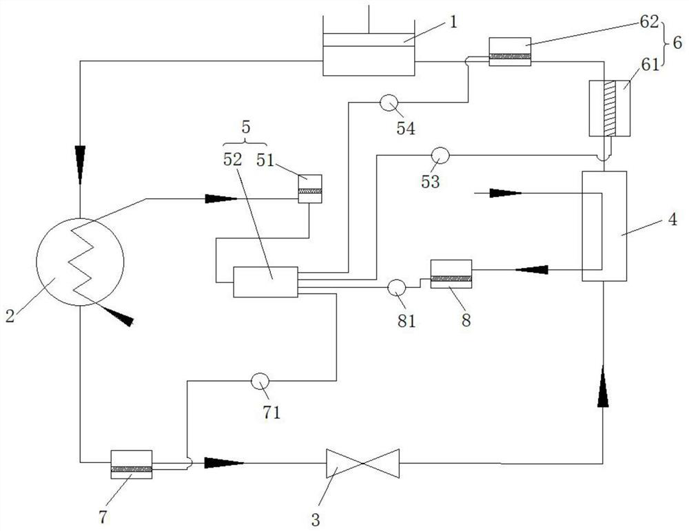
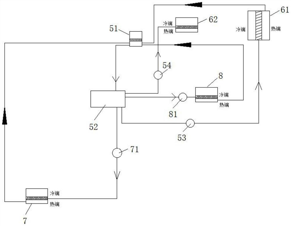
[0042] This embodiment provides a refrigeration system, such as figure 1 and figure 2 As shown, the refrigeration system includes a compressor 1, a condenser 2, a throttle valve 3, and an evaporator 4, an inlet connection of the compressor 1 and the inlet of the condenser 2 and the inlet of the throttle valve 3. Connect, the outlet of the throttle valve 3 is connected to the inlet of the evaporator 4, and the outlet of the evaporator 4 is connected to the suction port of the compressor 1;

[0043] The refrigeration system also includes an electric storage assembly 5 disposed on the wind side of the condenser 2 and a semiconductor refrigeration assembly 6 disposed between the compressor 1 and the evaporator 4, and the power storage component 5 recovers the heat release of the condenser 2 for use in The semiconductor refrigeration assembly 6 provides electrical energy, and the semiconductor refrigeration assembly 6 is used to adjust the suction overheating value of the compressor 1....

Embodiment 2

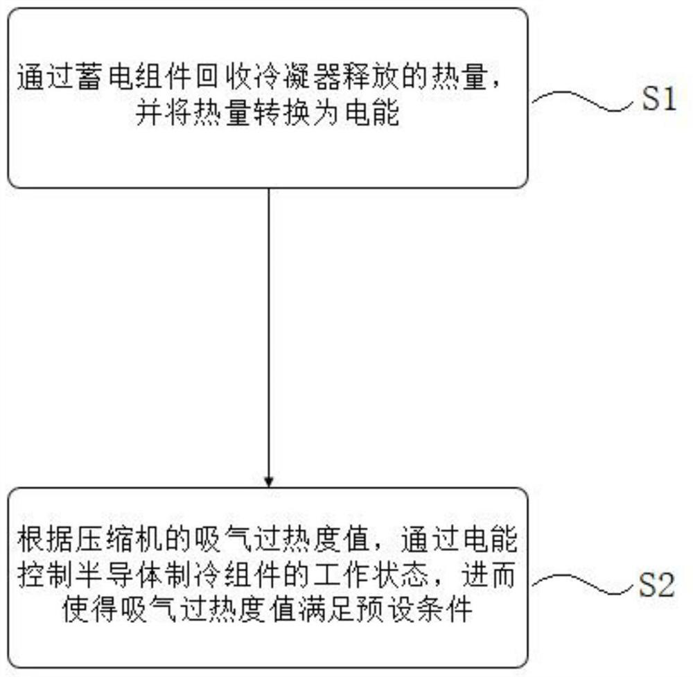
[0084] This embodiment provides a method of controlling a refrigeration system, such as image 3 As shown, the control method includes the steps of:

[0085] S1, the calorifier 2 released by the power storage component 5 and converts heat into electrical energy;

[0086] S2, according to the suction overheating value of the compressor 1, by the electrical energy controls the working state of the semiconductor refrigeration assembly 6, thereby causing the suction overheating value to satisfy the preset conditions.

[0087] In the specific embodiment:

[0088] The calorifier 2 released by the power storage component 5, and the heat is converted into electrical energy, specifically:

[0089] The heat released by the condenser 2 increases the temperature of the hot end of the semiconductor temperature difference generator 51 to generate electrical energy through the temperature difference of the cold end through the hot end of the semiconductor temperature difference generator 51 and t...

Embodiment 3

[0100] This embodiment provides an air conditioner that includes a refrigeration system in Example 1.


PUM


Abstract

The invention discloses a refrigerating system, a control method and an air conditioner. The refrigerating system comprises a compressor, a condenser, a throttling valve and an evaporator which are sequentially connected end to end. The electric power storage assembly is arranged on the air outlet side of the condenser, and the semiconductor refrigeration assembly is arranged between the compressor and the evaporator. The electricity storage assembly is arranged on the air outlet side of the condenser and used for recycling heat released by the condenser and converting the heat into electricity, and the greenhouse effect caused by the heat is avoided; in addition, the electric energy source of the semiconductor refrigeration assembly is heat released by the condenser, and therefore waste heat utilization of condensation heat is further achieved; the semiconductor refrigeration assembly can adjust the air suction superheat degree value of the compressor, the situation that when the air suction superheat degree is too high, the exhaust temperature and exhaust pressure of the compressor exceed specified values is avoided, and meanwhile the situation that when the air suction superheat degree is low or even lower than 0 DEG C, an inlet of the compressor contains liquid refrigerants, and the liquid impact phenomenon of the compressor occurs is avoided. And the service life of the compressor is influenced.

Description

Technical field [0001] The present invention relates to the field of refrigeration techniques, and more particularly to a refrigeration system, a control method, and an air conditioner. Background technique [0002] The refrigeration system is typically composed of four main components of the evaporator, a compressor, a condenser, and an expansion valve, sequentially connected by a line to a closed cycle system. The liquid refrigerant absorbs heat of the cooling space or the heat of the cooled object in the evaporator, gasifier into a low temperature and low pressure gas refrigerant, is inhaled by the compressor, and is discharged into a condenser, in the condenser, in the condenser The medium-to-cooling medium (air) is exothermic, condensing is a high pressure liquid refrigerant, and the expanded valve fertilizer is a low temperature low pressure liquid refrigerant, and then enters the evaporator in the evaporator to heat the gasification to achieve the purpose of circulating re...

Claims


Application Information

Patent Timeline
IPC IPC(8): F25B25/00F25B49/00F24F5/00F24F12/00F24F11/64F24F11/70H02N11/00
CPCF25B25/00F25B49/00F24F5/001F24F5/0042F24F12/00F24F11/64F24F11/70H02N11/002F25B2321/02
Inventor 王振雨罗胜杨蓉
Owner GREE ELECTRIC APPLIANCES INC OF ZHUHAI
Learn More