

Discharging circuit, energy router, frequency converter, centrifugal machine and centrifugal machine air conditioner
A discharge circuit and router technology, applied in the modification of power electronics, electrical components, conversion equipment for intermediate conversion to DC, etc., can solve problems such as poor heat dissipation, waste of electric energy, etc., to improve reliability and safety Effect
- Summary
- Abstract
- Description
- Claims
- Application Information
AI Technical Summary
Problems solved by technology
Method used
Image

Examples
Embodiment 1
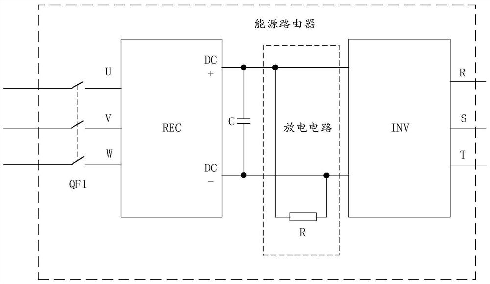
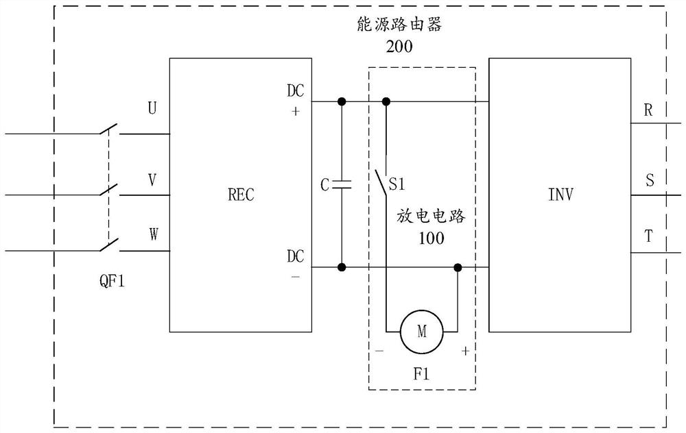
[0033] figure 2 is a schematic diagram of a discharge circuit 100 shown according to an exemplary embodiment, such as figure 2 As shown, the discharge circuit 100 includes:
[0034] The cooling device F1 is connected in parallel to both ends of the DC support capacitor C of the DC bus.
[0035] It should be noted that the technical solution provided in this embodiment is applicable to application scenarios where DC support capacitors need to be discharged, including but not limited to: discharging DC support capacitors of energy routers.
[0036] In a specific practice, the heat dissipation device F1 may be a heat dissipation fan.
[0037] Since the DC power stored in the DC support capacitor C is DC, the cooling fan is a DC fan. see figure 2 , DC+ is the positive pole of the DC bus, and DC- is the negative pole of the DC bus. As shown in the dotted line box in the figure, the negative pole of the cooling device F1 is connected to DC-, and the positive pole is connected...
Embodiment 2
[0055] see figure 2 , an energy router 200 shown according to an exemplary embodiment, comprising:
[0056] The discharge circuit 100 described above.
[0057] It should be noted that the technical solutions provided in this embodiment are applicable to electrical equipment installed with energy routers, including but not limited to frequency converters.
[0058] It can be understood that, in the technical solution provided by this embodiment, since the energy router includes the discharge circuit described in Embodiment 1, and the discharge circuit consumes the residual electric energy in the support capacitor by connecting the cooling device in parallel to both ends of the support capacitor, thereby Realize the discharge of the residual electric energy in the support capacitor, and at the same time, the heat dissipation device can also dissipate heat to the surrounding environment, which is equivalent to not only realizing the discharge, but also realizing energy saving, w...
Embodiment 3
[0061] A frequency converter shown according to an exemplary embodiment includes:
[0062] The aforementioned energy router.
[0063] It should be noted that the technical solutions provided in this embodiment are applicable to electrical equipment installed with frequency converters, including but not limited to: centrifuges.
[0064] It can be understood that, in the technical solution provided by this embodiment, since the frequency converter includes the discharge circuit described in Embodiment 1, and the discharge circuit consumes the residual electric energy in the support capacitor by connecting the cooling device in parallel to both ends of the support capacitor, thereby Realize the discharge of the residual electric energy in the support capacitor, and at the same time, the heat dissipation device can also dissipate heat to the surrounding environment, which is equivalent to not only realizing the discharge, but also realizing energy saving, which solves the problem ...
PUM
 Abstract
Description
Claims
Application Information