Automatic monitoring device for brightness change of pulse width modulation lamp

A brightness change and automatic monitoring technology, applied in the direction of measuring devices, measuring electrical variables, energy-saving control technology, etc., can solve the problems of easy fatigue of personnel, changes in the brightness of PWM lamps, low work efficiency, etc., to achieve automatic monitoring of brightness changes, accurate The effect of shaping transformations

Pending Publication Date: 2022-03-01
GUANGZHOU GRG METROLOGY & TEST CO LTD
View PDF0 Cites 0 Cited by
  • Summary
  • Abstract
  • Description
  • Claims
  • Application Information

AI Technical Summary

Problems solved by technology

[0007] 1. The photoelectric conversion monitoring method in the electromagnetic compatibility immunity test is no longer suitable for monitoring the brightness change of PWM lamps;
[0008] 2. Using an oscilloscope to continuously monitor the numerical changes of frequency and duty cycle requires staff to witness the oscilloscope screen for a long time, which leads to high cost, low work efficiency and fatigue

Method used


Image

  • Automatic monitoring device for brightness change of pulse width modulation lamp
  • Automatic monitoring device for brightness change of pulse width modulation lamp
  • Automatic monitoring device for brightness change of pulse width modulation lamp

Examples


Embodiment 1

[0069] According to a specific embodiment of the present invention, the automatic monitoring device for the brightness change of the pulse width modulation lamp of the present invention will be described in detail with reference to the accompanying drawings.

[0070] The invention provides an automatic monitoring device for brightness changes of pulse width modulation lamps, including:

[0071] Photoelectric conversion circuit, waveform shaping circuit and microprocessor operation circuit;

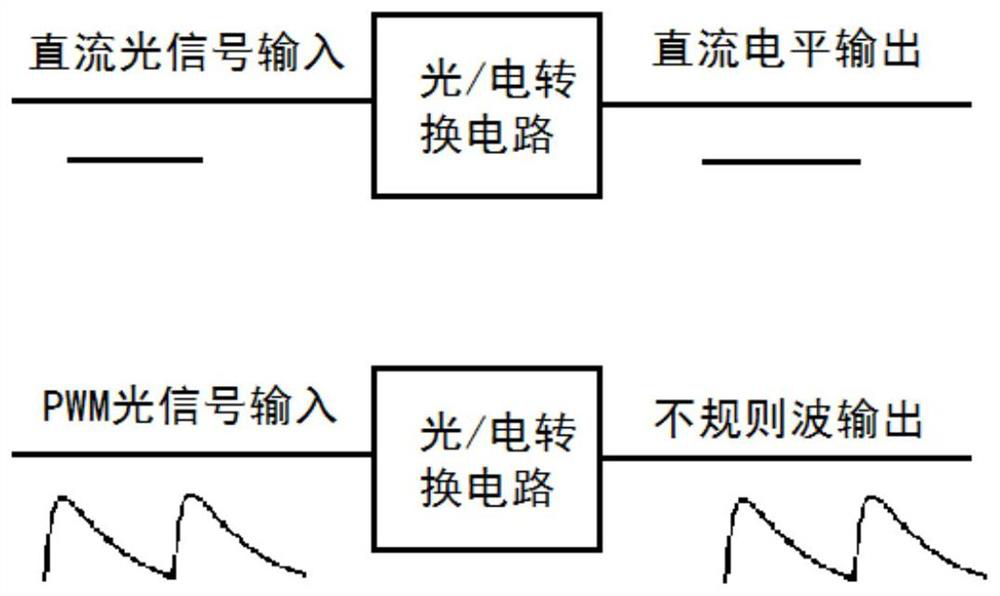
[0072] The photoelectric conversion circuit converts the input PWM optical signal into an electrical signal;

[0073] The waveform shaping circuit performs waveform shaping on the input PWM electrical signal;

[0074] The microprocessor operation circuit performs the following operations:

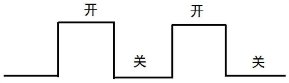
[0075] Collect the first positive pulse width time X1 and the first waveform cycle time Y1 after shaping, and set the first positive pulse width time X1 and the first waveform cycle time Y1 as the pul...

Embodiment 2

[0079] According to a specific embodiment of the present invention, the automatic monitoring device for the brightness change of the pulse width modulation lamp of the present invention will be described in detail with reference to the accompanying drawings.

[0080] The invention provides an automatic monitoring device for brightness changes of pulse width modulation lamps, including:

[0081] Photoelectric conversion circuit, waveform shaping circuit and microprocessor operation circuit, also including DC voltage stabilization circuit;

[0082] The photoelectric conversion circuit converts the input PWM optical signal into an electrical signal; the photoelectric conversion circuit includes a first diode, a first capacitor, a first resistor, a second resistor, a third resistor, a fourth resistor, a sixth switch and a Seven switches, one end of the first capacitor is connected to the PWM input signal and the first diode, and the other end is grounded; after the first resistor,...

Embodiment 3

[0097] According to a specific embodiment of the present invention, the calculation process of each parameter in the present invention will be described in detail with reference to the accompanying drawings.

[0098] Such as Figure 7 Shown in is the parameter setting of each element in the photoelectric conversion circuit in a specific embodiment of the present invention, the resistance value linear change range of photosensitive diode (the first diode) Rd1 is about between 5KΩ to 100Ω, in order to ensure that the photosensitive device Work in the best line core range, the minimum output voltage of point A in the circuit should be about 0.5 times the power supply VCC voltage, that is, 2.5V, and the maximum output voltage should be about 0.9 times VCC, that is, 4.5V, and at the same time, it should meet the requirements of different brightness Optical signal input, the circuit is implemented by resistor division with different gears. When the optical signal input is weak, the ...


PUM


Abstract

The invention provides an automatic monitoring device for the brightness change of a pulse width modulation lamp, and belongs to the technical field of LED lamps. The invention provides an automatic monitoring device for brightness change of a pulse width modulation lamp. The automatic monitoring device comprises a photoelectric conversion circuit, a waveform shaping circuit and a microprocessor operational circuit, the photoelectric conversion circuit is used for converting an input PWM optical signal into an electric signal; the waveform shaping circuit performs waveform shaping on the input PWM electric signal; the microprocessor operational circuit is used for setting a pulse width time reference, a waveform period reference and an allowance range according to a first positive pulse width time and a first waveform period time of the collected shaped signal; the input signal is captured in real time, the pulse width time and the waveform period of the signal are compared with the allowance range, and an alarm is given when the pulse width time and the waveform period exceed the allowance range. According to the invention, automatic monitoring of the brightness change of the LED lamp is realized, and the blank in the field of automatic monitoring of the brightness change of the LED lamp at present is filled.

Description

technical field [0001] The invention relates to the technical field of LED lamps, in particular to an automatic monitoring device for brightness changes of pulse width modulation lamps. Background technique [0002] With the continuous development of LED lighting production and manufacturing technology, the application of LED lighting in the fields of household appliances, automobiles, aviation and navigation, and medical equipment is becoming more and more popular. At the same time, product testing standards are also constantly improving. Detection technology puts forward higher requirements. [0003] In the design of LED lamps, in order to improve the service life of beads, the circuit of most lamps will adopt the lighting method of pulse width modulation (PWM), and the frequency range is usually between 200-1000 Hz. Pulse width modulation is to make the LED lamp bead turn on for a period of time, and then turn off for a period of time (such as figure 1 ), over and over ...

Claims


Application Information

Patent Timeline
Patent Type & Authority Applications(China)
IPC IPC(8): H05B45/10H05B45/30H05B45/325H05B45/37H05B45/50H05B45/34G01R31/00
CPCH05B45/10H05B45/30H05B45/325H05B45/37H05B45/50H05B45/34G01R31/001Y02B20/40
Inventor 张雄代勇
Owner GUANGZHOU GRG METROLOGY & TEST CO LTD
Why Eureka
Try Eureka