Multi-stage dehumidification device, waste gas treatment system and dehumidification control method

A waste gas treatment and humidity technology, applied in the direction of gas treatment, separation methods, non-electric variable control, etc., can solve the problems of water accumulation in the acid discharge pipeline at the plant service end, high replacement cost of dehumidification devices, and accelerated gas cooling and drying. Achieve the effect of facilitating equipment transformation, improving equipment dehumidification capacity, and accelerating cooling and drying

Active Publication Date: 2022-03-04
BEIJING JINGYI AUTOMATION EQUIP CO LTD
View PDF8 Cites 0 Cited by
  • Summary
  • Abstract
  • Description
  • Claims
  • Application Information

AI Technical Summary

Problems solved by technology

[0008] The invention provides a multi-stage dehumidification device, waste gas treatment system and dehumidification control method, which are used to solve the problem of high replacement cost of dehumidification devices in the related art, ineffective dehumidification effect, water accumulation in the acid discharge pipeline at the factory service end, and high risk of bruising The ...

Method used


Image

  • Multi-stage dehumidification device, waste gas treatment system and dehumidification control method
  • Multi-stage dehumidification device, waste gas treatment system and dehumidification control method

Examples


Embodiment Construction

[0035] Embodiments of the present invention will be further described in detail below in conjunction with the accompanying drawings and examples. The following examples are used to illustrate the present invention, but should not be used to limit the scope of the present invention.

[0036] In the description of the embodiments of the present invention, it should be noted that the terms "center", "longitudinal", "transverse", "upper", "lower", "front", "rear", "left", "right" , "vertical", "horizontal", "top", "bottom", "inner", "outer" and other indicated orientations or positional relationships are based on the orientations or positional relationships shown in the drawings, and are only for the convenience of describing this The embodiments and simplified descriptions of the invention do not indicate or imply that the devices or elements referred to must have a specific orientation, be constructed and operate in a specific orientation, and therefore should not be construed a...


PUM


Abstract

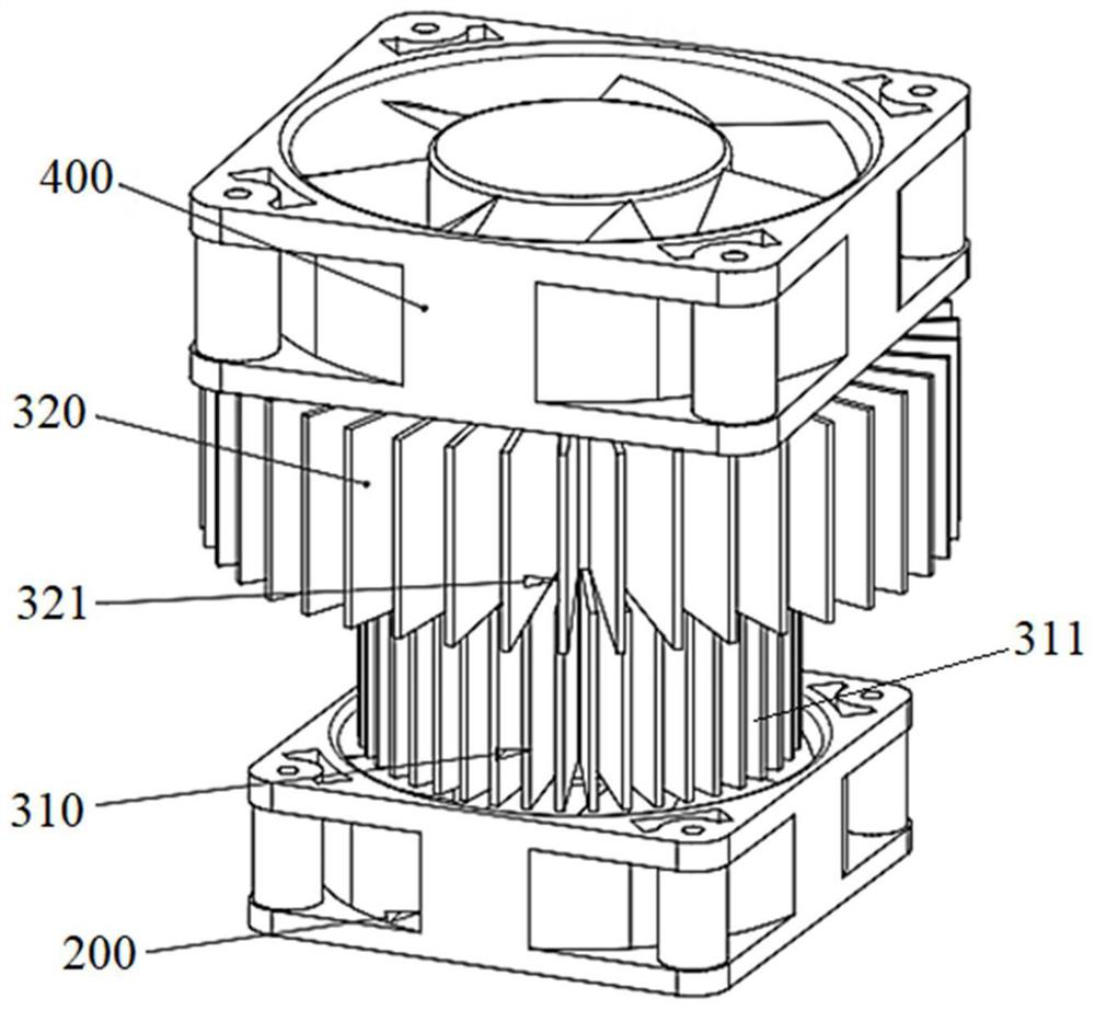
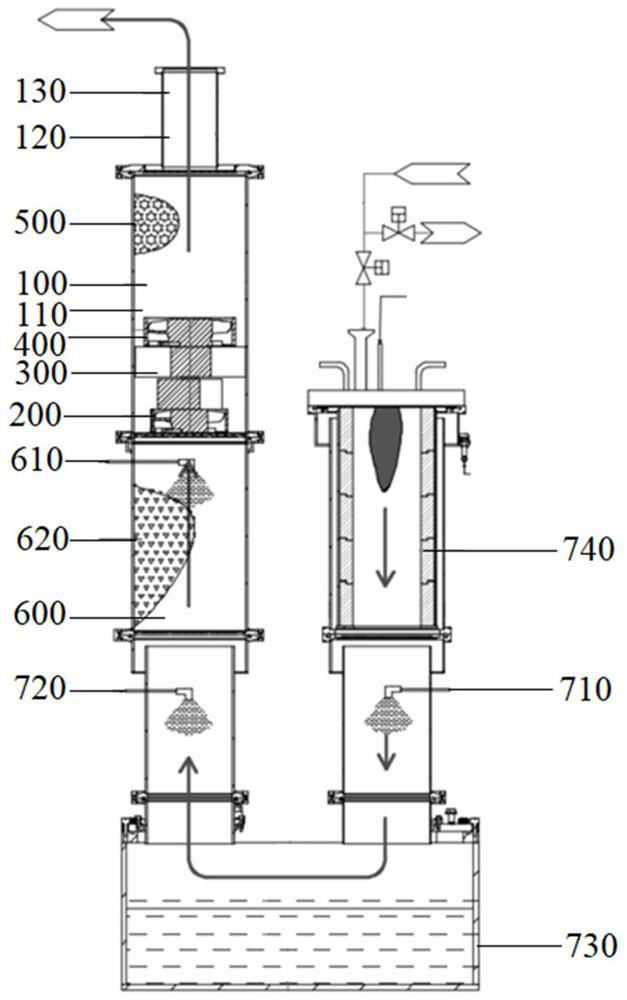
The invention relates to the technical field of semiconductors, in particular to a multi-stage dehumidification device, a waste gas treatment system and a dehumidification control method.The multi-stage dehumidification device comprises a shell, a first fan, a heat exchange assembly and a second fan, the first fan, the heat exchange assembly and the second fan are located in the shell and sequentially arranged in the flow direction of gas in the shell, and the first fan, the heat exchange assembly and the second fan are coaxially arranged. Gas is cooled at the heat exchange assembly, moisture in the gas is condensed, the convection effect of gas flowing is enhanced through the first fan and the second fan, cooling and drying of the gas are accelerated, the dehumidification effect on the gas is achieved, and the exhausted gas meets the temperature and humidity requirements. The multi-stage dehumidification device can be directly installed in a waste gas treatment system under the condition that negative pressure is not affected, the dehumidification effect is achieved, existing equipment can be conveniently transformed, and the machine replacement cost required by factory dehumidification is reduced. The requirements for temperature and humidity in the semiconductor manufacturing process are met, the dehumidification capacity of equipment is improved, and the risks of falling of accumulated water and high-risk crushing of an acid discharge pipeline at a factory service end are reduced.

Description

technical field [0001] The invention relates to the technical field of semiconductors, in particular to a multi-stage dehumidification device, a waste gas treatment system and a dehumidification control method. Background technique [0002] Pan-semiconductor process exhaust gas contains a large amount of toxic and harmful gases. With different manufacturing processes, the amount of dust is also different, especially the dust content of metals is relatively high, so the exhaust gas treatment equipment basically adopts high-temperature cracking or reaction, plus washing, spraying and cooling. The method is to eliminate toxic substances in the exhaust gas and reduce dust. The requirement for temperature and humidity is that when the production process has no temperature and humidity requirements, the control temperature is 20-26°C and the relative humidity is lower than 70%. Therefore, the following problems exist in the waste gas treatment process: [0003] 1. When the exhaus...

Claims


Application Information

Patent Timeline
IPC IPC(8): B01D53/26B01D47/14B01D53/30F28C1/02G05D27/02
CPCB01D53/265B01D53/261B01D53/30F28C1/02B01D47/14G05D27/02B01D2259/4009B01D2258/0283B01D2253/106
Inventor 杨春水宁腾飞章文军张坤陈彦岗杨春涛王继飞席涛涛闫潇
Owner BEIJING JINGYI AUTOMATION EQUIP CO LTD
Why Eureka
Try Eureka