
Clamping tool for track link section finish machining

A technology for clamping tooling and chain rail links, which is applied to metal processing equipment, metal processing machine parts, clamping, etc., and can solve problems affecting the processing accuracy of chain rail links

Pending Publication Date: 2022-03-04
钢客履带(江苏)有限公司
View PDF0 Cites 0 Cited by
  • Summary
  • Abstract
  • Description
  • Claims
  • Application Information

AI Technical Summary

Problems solved by technology

Due to the irregular shape of the chain rail joints, the existing device is not convenient to clamp and fix the chain rail joints when the chain rail joints are finished, which affects the machining accuracy of the chain rail joints when they are finished.

Method used


Image

  • Clamping tool for track link section finish machining
  • Clamping tool for track link section finish machining
  • Clamping tool for track link section finish machining

Examples


Embodiment

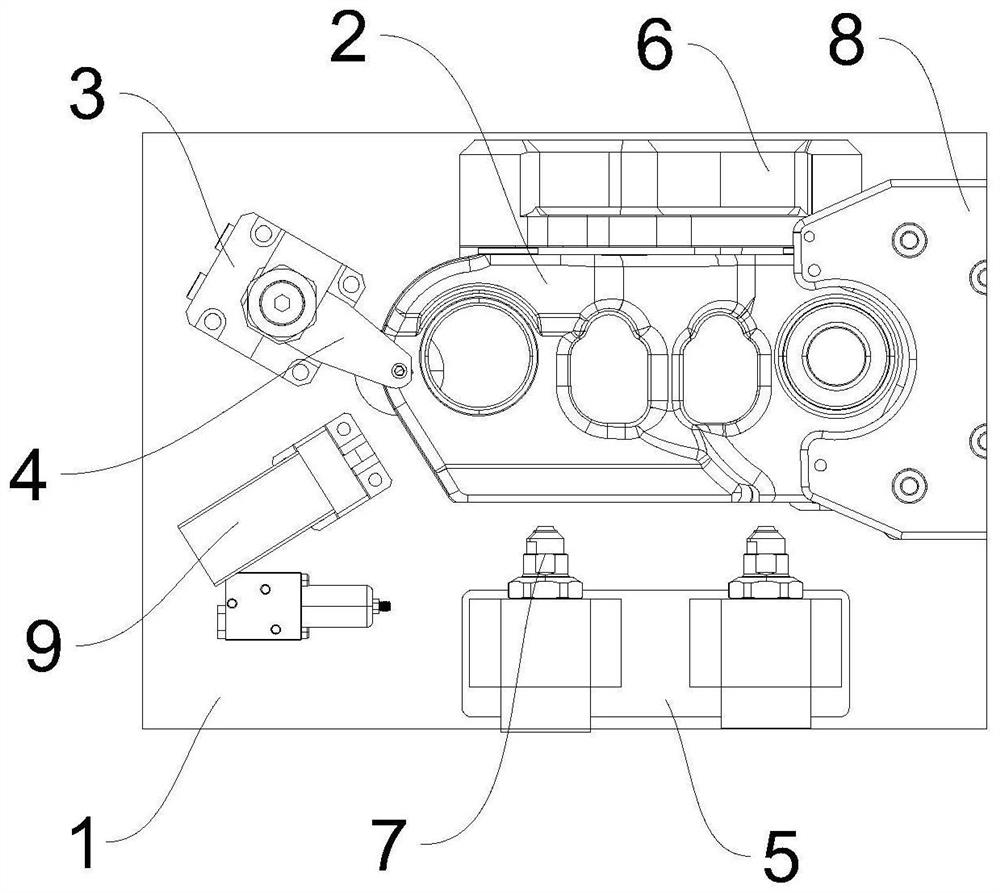
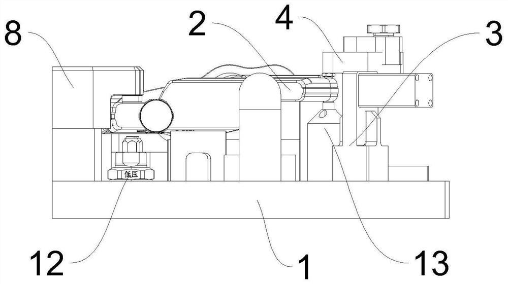
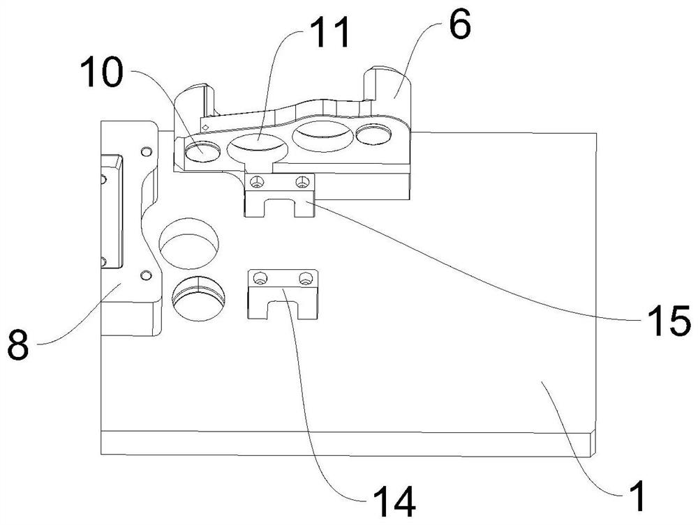
[0032] Please refer to Figure 1-Figure 3 shown. This embodiment provides a clamping tool for the finishing of chain rail links, including a mounting base 1, a first hydraulic cylinder 13 disposed on one side of the mounting base 1, and a second hydraulic cylinder 12 disposed on the other side of the mounting base 1, One side of the installation base plate 1 is provided with a rotary cylinder 3 that cooperates with the first hydraulic cylinder 13, and the output end of the rotary cylinder 3 is connected with a rotary platen 4, and the other side of the installation base plate 1 is provided with a limiter that cooperates with the second hydraulic cylinder 12. bit piece 8.

[0033]In the above-mentioned embodiment, the clamping tool for the finishing of the chain rail link 2 is composed of the installation base plate 1, the first hydraulic cylinder 13 and the second hydraulic cylinder 12, wherein the first hydraulic cylinder 13 is located on one side of the installation base pl...


PUM


Abstract

The invention provides a clamping tool for caterpillar track section finish machining, and relates to the technical field of caterpillar track section machining equipment. According to the scheme, the clamping tool for caterpillar link section finish machining comprises a mounting base plate, a first hydraulic oil cylinder arranged on one side of the mounting base plate and a second hydraulic oil cylinder arranged on the other side of the mounting base plate, a rotating cylinder matched with the first hydraulic oil cylinder is arranged on one side of the mounting base plate, and the output end of the rotating cylinder is connected with a rotating pressing plate; and a limiting piece matched with the second hydraulic oil cylinder is arranged on the other side of the mounting base plate. The caterpillar track section can be clamped and fixed during finish machining of the caterpillar track section, and the machining precision of the caterpillar track section during finish machining is improved.

Description

technical field [0001] The invention relates to the technical field of chain rail link processing equipment, in particular to a clamping tool for finishing the chain rail link. Background technique [0002] The chain rail link is the part used to connect the track used in construction machinery such as excavators and bulldozers and military machinery such as tanks. The material used for chain rail links is generally 35MnBM, which has very good hardenability. The model of the chain link is determined according to the center distance of the two holes, mainly 135, 154, 171, 190, 228, etc., such as figure 1 and figure 2 As shown, the two holes of the chain rail link are generally one large and one small, the large hole is a sleeve hole, and the small hole is a pin hole. [0003] The manufacturing process of the chain rail link is generally: bar sawing - heating - forging - residual heat quenching - cooling - magnetic particle inspection - milling end face - high frequency qu...

Claims


Application Information

Patent Timeline
Patent Type & Authority Applications(China)
IPC IPC(8): B23Q3/08
CPCB23Q3/082
Inventor 刘国义于大江王珂王成琦
Owner 钢客履带(江苏)有限公司
Learn More