Polluted soil in-situ chemical barrier material and preparation and application thereof

A technology of polluted soil and barrier materials, applied in the restoration of polluted soil, etc., can solve the problems of reducing the content of pollution factors, restricting construction, pollution exposure, etc., and achieve the effects of long-lasting performance, convenient material acquisition, and multiple functions

Pending Publication Date: 2022-03-11
辽宁中博生态环境技术有限公司
View PDF10 Cites 1 Cited by
  • Summary
  • Abstract
  • Description
  • Claims
  • Application Information

AI Technical Summary

Problems solved by technology

However, the disadvantage of in-situ barrier control is that it does not effectively reduce the content of pollution factors, and there is a risk of damage and pollution exposure. At the same time, it also restricts the subsequent planning and construction of the site to a certain extent.

Method used


Image

  • Polluted soil in-situ chemical barrier material and preparation and application thereof
  • Polluted soil in-situ chemical barrier material and preparation and application thereof
  • Polluted soil in-situ chemical barrier material and preparation and application thereof

Examples


Embodiment 1

[0046] The preparation of embodiment 1 polluted site chemical barrier layer material

[0047] This example is aimed at the application of in-situ barrier control of heavy metal and organic pollutant compound polluted soil:

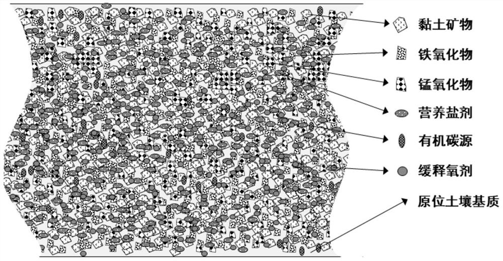
[0048] Accordingly, the chemical barrier material is composed of "in-situ soil + clay mineral + heavy metal stabilization active material + biostimulation active material". The schematic diagram of the chemical barrier material is as follows: figure 1 As shown, the composition of each component of the material is shown in Table 1.

[0049] 1) Preparation of chemical barrier materials

[0050] First, the in-situ soil was used as the matrix of the chemical barrier material, and the in-situ soil was excavated from a contaminated site of a chemical plant in the north. The soil pollution in the site was characterized by heavy metal arsenic exceeding the "Soil Environmental Quality Construction Land Soil Pollution Risk Control Standard" (GB 36600-2018), the sc...

Embodiment 2

[0070] Example 2 Chemical barrier layer used in pilot field barrier control of heavy metal arsenic-contaminated soil

[0071] According to the disposition result of the chemical barrier layer verified by the small test experiment in step 2) of embodiment 1, the sampling site of the polluted soil sample in the chemical barrier material matrix in the chemical barrier material matrix prepared in step 1) of embodiment 1 (a chemical industry in the north) A 5m long and 5m wide area in the factory polluted site) was selected to carry out the pilot test of contaminated soil isolation. During the construction process, the polluted target area was first cleared and excavated, and a flat-bottomed foundation pit with a length of 7m, a width of 7m and a depth of 800mm was excavated ( Figure 7 ), and then adopt the chemical barrier material prepared in step 1) of Example 1 as the chemical barrier layer, the thickness of the barrier layer is designed to be 0.5m, and the total amount of fil...


PUM


Abstract

The invention belongs to the technical field of in-situ risk control and remediation of contaminated soil, and particularly relates to an in-situ chemical barrier material for heavy metal, organic and compound contaminated soil, a preparation method of the in-situ chemical barrier material and application of the in-situ chemical barrier material to collaborative control and remediation treatment of the contaminated soil and underground water. The material comprises the following components in percentage by weight: 50-95% of in-situ soil in a polluted area and 5-50% of clay mineral. The chemical barrier layer material provided by the invention has the advantages of convenience in material obtaining, multiple functions, lasting performance, convenience in operation, wide application and the like. In-situ clean soil or soil meeting the landfill disposal standard is used as a main matrix material, the economic cost of materials is saved, meanwhile, clay minerals are added into the barrier material, the permeability coefficient of the barrier mixed material is remarkably reduced, in addition, pollution factors are effectively controlled and reduced in an auxiliary mode through application of active materials in the mixed material, and the environmental pollution is reduced. Therefore, the in-situ risk management and control and disposal targets of the polluted site are realized through multiple functional characteristics.

Description

technical field [0001] The invention belongs to the technical field of in-situ risk control and restoration of polluted soil, and specifically relates to an in-situ chemical barrier material for heavy metal, organic and compound polluted soil, a preparation method thereof, and an application for collaborative control and restoration of polluted soil and groundwater . Background technique [0002] The contaminated soil on the site comes from the production and operation activities of the petrochemical, coking and smelting, electronic pharmaceutical and other industrial factories in the early stage and long-term operation. As the protection of the ecological environment is getting more and more attention, the supporting measures for environmental protection in the production process of industrial enterprises are constantly improving, supplemented by the continuous expansion of the supervision of enterprises in key industries related to environmental interference, and the pollu...

Claims


Application Information

Patent Timeline
Patent Type & Authority Applications(China)
IPC IPC(8): B09C1/00B09C1/08
CPCB09C1/002B09C1/08B09C2101/00
Inventor 王卅黄殿男吴阳
Owner 辽宁中博生态环境技术有限公司
Why Eureka
Try Eureka