
Full-compliant impact-overload-resistant dynamic mass compensation micro-positioning device

A dynamic mass, micro-positioning technology, used in maintenance and safety accessories, measuring/indicating equipment, metal processing equipment, etc., can solve problems such as limiting the working stroke of the micro-positioning motion platform, inability to take into account positioning accuracy, and system heating, etc. It does not affect the positioning accuracy and dynamic performance, the effect of simple structure and high motion accuracy

Active Publication Date: 2022-03-11
NAT UNIV OF DEFENSE TECH
View PDF4 Cites 0 Cited by
  • Summary
  • Abstract
  • Description
  • Claims
  • Application Information

AI Technical Summary

Problems solved by technology

[0004] In the prior art, a large-output driving device or a high-rigidity supporting transmission structure is usually used to resist strong vibration and strong impact overload, but the problem is that the large-output driving device outputs high power for a long time, which makes the system seriously heated , high power consumption, and positioning accuracy cannot be taken into account at the same time; or the high-rigidity supporting transmission structure limits the working stroke of the micro-positioning motion platform, so that the system can only achieve accurate positioning at the nanometer or submicron level

Method used


Image

  • Full-compliant impact-overload-resistant dynamic mass compensation micro-positioning device
  • Full-compliant impact-overload-resistant dynamic mass compensation micro-positioning device
  • Full-compliant impact-overload-resistant dynamic mass compensation micro-positioning device

Examples


Embodiment Construction

[0027] The present invention will be further described in detail below in conjunction with the accompanying drawings and specific embodiments.

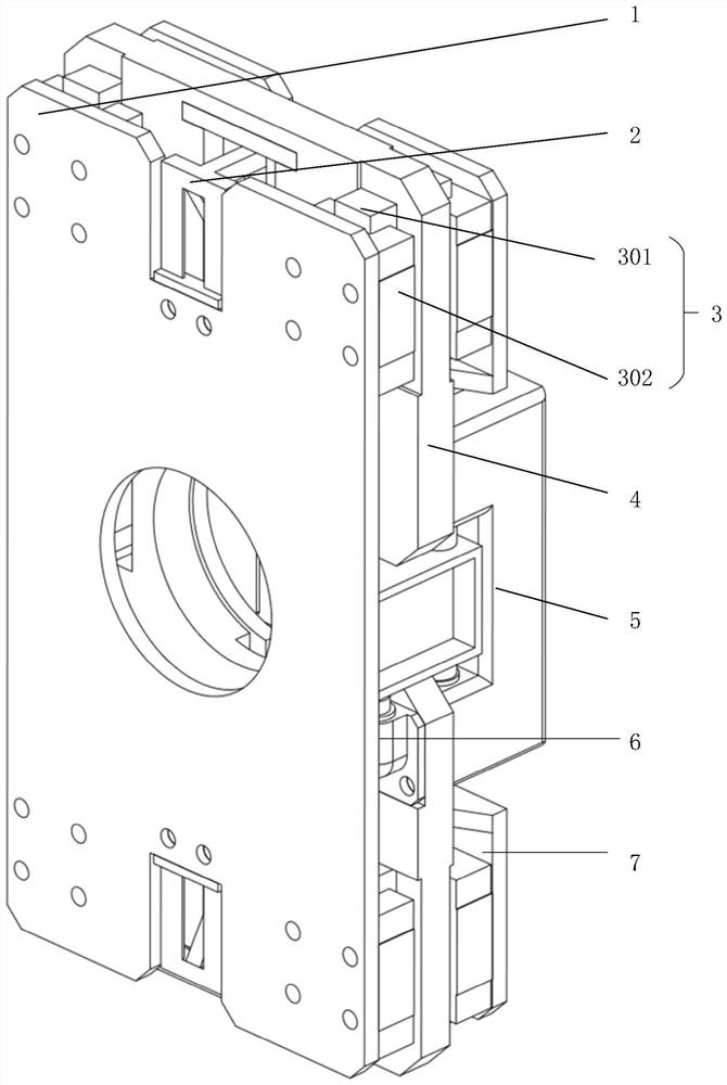
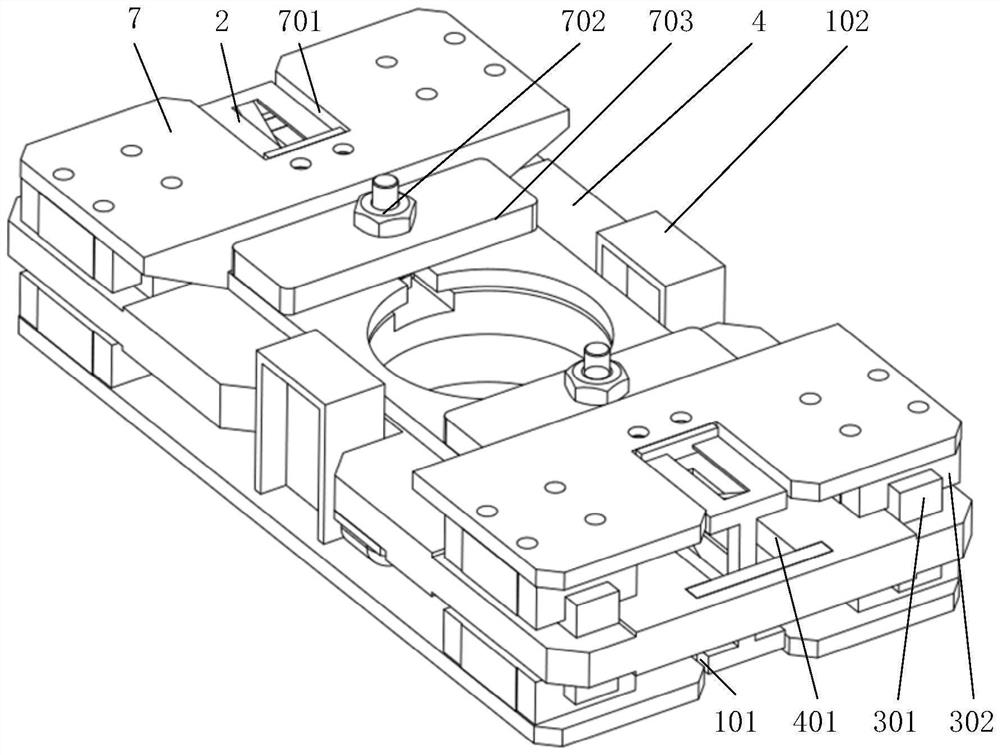
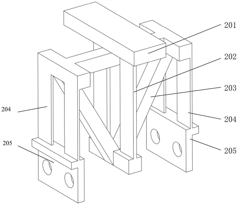
[0028] Such as figure 1 with figure 2 As shown, the fully compliant and shock-resistant dynamic mass compensation micro-positioning device of the present invention includes a compliant lever mechanism 2, a motion platform 1, a mass counterweight platform 7, a base 4, multiple sets of guide rail slider assemblies 3, a driver 5 and The sensor 6; the rigid fulcrum crossbeam 201 of the compliant lever mechanism 2 is fixed on the base 4, and the motion platform 1 and the mass counterweight platform 7 pass through the multiple sets of guide rail slider assemblies 3 and the base 4 respectively. Both sides are connected, and translational freedom in one direction is reserved; the left and right ends of the compliant lever mechanism 2 are fixedly connected with the motion platform 1 and the mass counterweight platform 7 respectively, and are...


PUM


Abstract

The invention discloses a full-compliance impact overload resistant dynamic mass compensation micro-positioning device which comprises a compliance lever mechanism, a motion platform, a mass balance weight platform, a base, a plurality of sets of guide rail sliding block assemblies, a driver and a sensor. The motion platform and the mass balance weight platform are connected with the two sides of the base through the multiple sets of guide rail sliding block assemblies respectively, and the translational degree of freedom in one direction is reserved. The left end and the right end of the compliant lever mechanism are fixedly connected with the motion platform and the mass balance weight platform respectively to form a full compliant dynamic mass compensation micro-positioning system. And the sensor is used for monitoring the displacement of the motion platform relative to the base in real time, so that the driver completes the driving action. The device has the advantages of simple structure, simplicity and convenience in operation, high positioning precision, large movement range and the like.

Description

technical field [0001] The invention mainly relates to the technical field of precision micro-positioning, in particular to a dynamic mass compensation micro-positioning device which is completely compliant and resists impact and overload. Background technique [0002] With the continuous expansion of disciplines in the fields of precision machining, space communication, optical engineering, and aerospace, precision micro-positioning technology has been widely used, and its application occasions and environments have become more and more diverse and complex. [0003] As one of the basic key technologies of micro-action, micro-measurement and micro-manufacturing, precision micro-positioning technology can satisfy high positioning accuracy, high dynamic performance, high resolution and strong stability, and can be used in complex, extreme or harsh environments. Normal work under environmental conditions has become a key factor for its wider and deeper application. For example...

Claims


Application Information

Patent Timeline
Patent Type & Authority Applications(China)
IPC IPC(8): B23Q11/00B23Q17/00
CPCB23Q11/0017B23Q17/00
Inventor 范世珣羊鹏谭若愚何强谢馨范大鹏
Owner NAT UNIV OF DEFENSE TECH
Learn More