Floating fan platform mounting method

An installation method and floating technology are applied in the field of floating fan platform installation, which can solve the problems of self-elevating installation platform configuration requirements, high construction cost, waste of resources, etc., so as to reduce installation cost, reduce comprehensive cost, and reduce offshore The effect of the difficulty of installation

Pending Publication Date: 2022-03-15
DALIAN SHIPBUILDING IND
View PDF0 Cites 0 Cited by
  • Summary
  • Abstract
  • Description
  • Claims
  • Application Information

AI Technical Summary

Problems solved by technology

In order to meet the above requirements, the configuration requirements and construction costs of the self-elevating installation platform will be very high
At the same time, due to the birth of this type of platform, the related facilities previously built for shallow water wind power installation will be forced to idle due to no installation work, resulting in waste of resources

Method used


Image

  • Floating fan platform mounting method
  • Floating fan platform mounting method
  • Floating fan platform mounting method

Examples


Embodiment 1

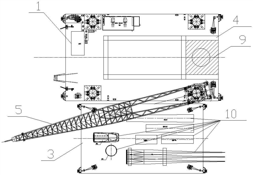
[0028] A method for installing a floating wind turbine platform, in which a self-elevating lifting platform is arranged in a shallow water area, a cantilever beam and a lifting crane are fixed on the self-elevating lifting platform, and a floating barge is docked beside the self-elevating lifting platform ,Such as figure 1 As shown, the wind turbine assembly is placed on the floating barge, and the crane lifts the wind turbine assembly to the cantilever beam. There is an installation area at the end of the cantilever beam. In the installation area of ​​the cantilever beam, the existing offshore wind power plant in shallow water can be used The wind turbines are assembled by piles and offshore wind turbine installation equipment.

[0029] The tugboat tows the floating wind turbine platform to the offshore mooring point, and connects the floating wind turbine platform to the offshore mooring point through mooring cables. type lifting platform, such as Figure 4 As shown, the p...

Embodiment 2

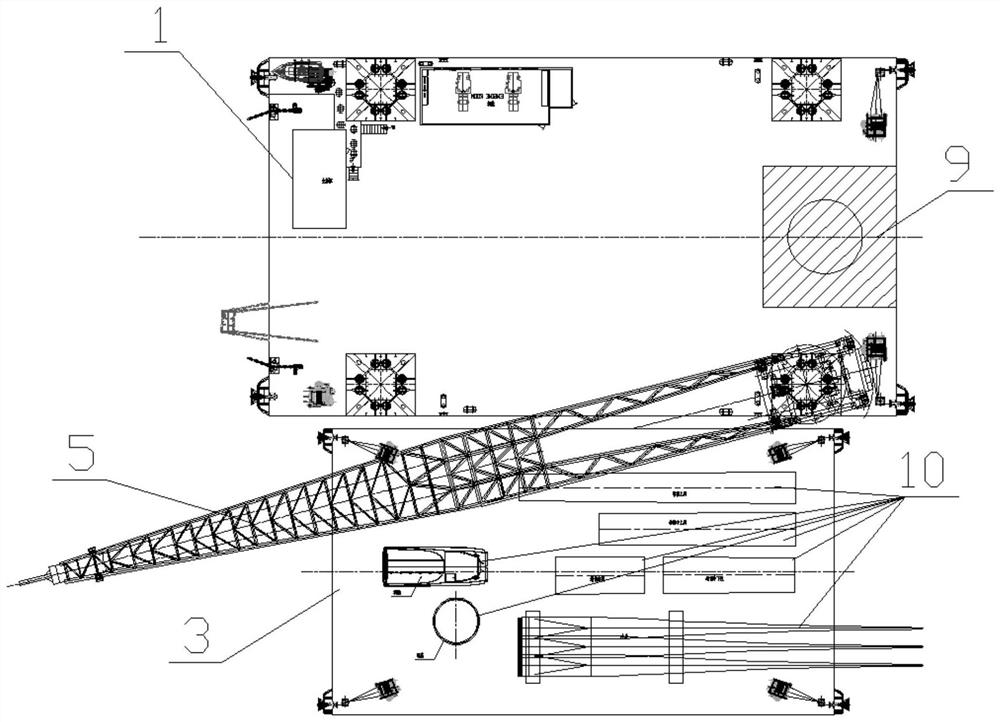
[0032] Such as figure 2 As shown in the figure, a self-elevating lifting platform is installed in the shallow water area, and a crane is fixed on the self-elevating lifting platform, and a floating barge is docked beside the self-elevating lifting platform, and the fan assembly is placed on the floating barge , the hoisting crane lifts the wind turbine components to the installation area of ​​the self-elevating lifting platform, and the hoisting crane lifts the wind turbine components to the installation area, using the existing offshore wind power piles and offshore wind turbine installation equipment in the installation area in shallow water Assemble the fan.

[0033] The tugboat tows the floating wind turbine platform to the offshore mooring point, and connects the floating wind turbine platform to the offshore mooring point through mooring cables. type lifting platform, such as Figure 4As shown, the pulling direction of the tugboat is opposite to that of the mooring ca...

Embodiment 3

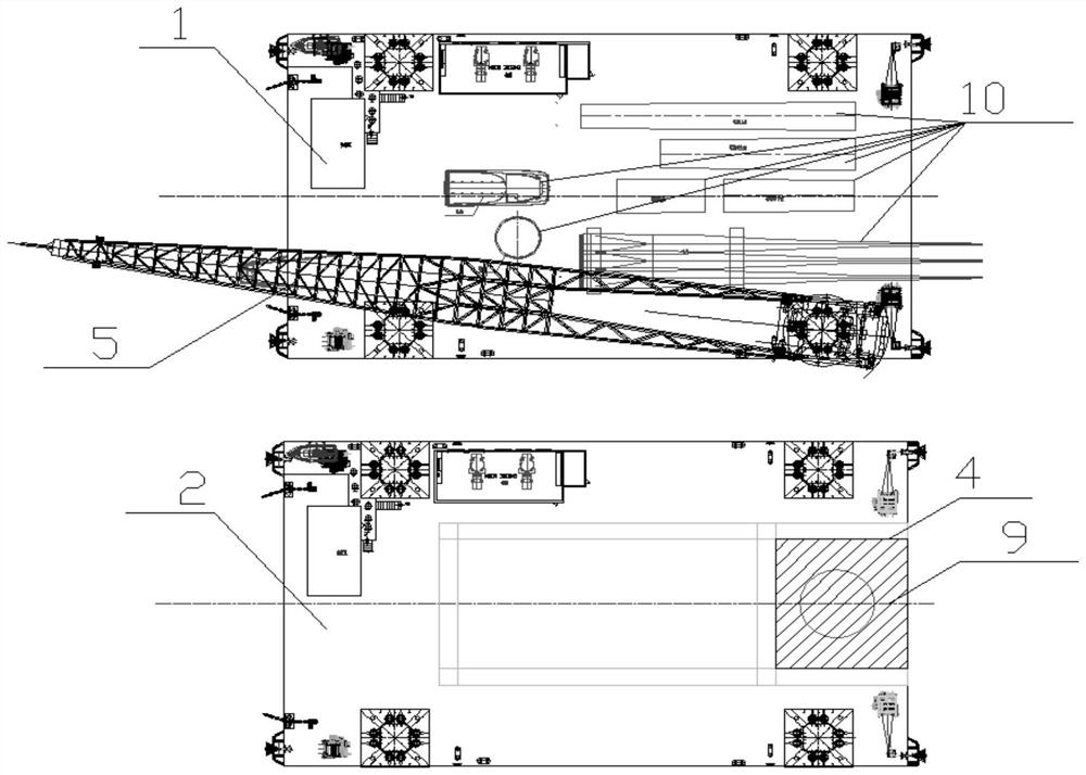
[0036] Such as image 3 As shown, a self-elevating lifting platform is set in the shallow water area, and a crane is fixed on the self-elevating lifting platform. On the lifting platform, a cantilever beam is fixed on the self-elevating auxiliary platform, and the end of the cantilever beam is provided with an installation area. , Offshore wind turbine installation equipment assembles the wind turbine in the installation area.

[0037] The tugboat tows the floating wind turbine platform to the offshore mooring point, and connects the floating wind turbine platform to the offshore mooring point through mooring cables. type lifting platform, such as Figure 4 As shown, the pulling direction of the tugboat is opposite to that of the mooring cable. Therefore, the tugboat and the mooring cable stabilize the floating wind turbine platform on the sea surface. After the floating wind turbine platform is stabilized, the installed wind turbine is transported to the floating On the wi...


PUM


Abstract

According to the floating type draught fan platform installation method, a self-elevating type lifting platform is arranged in a shallow water area, a lifting crane and a cantilever beam are fixed to the self-elevating type lifting platform, and a draught fan assembly is placed on a floating type barge. The lifting crane lifts the fan assembly to the cantilever beam for installation, the tugboat drags the floating fan platform to a shallow water area from the shore side, one end of the floating fan platform is connected with an offshore mooring point through a mooring rope, and the tugboat continues to drag the floating fan platform to the position beside the self-elevating lifting platform at the other end. And the cantilever beam conveys the assembled fan to the floating fan platform for installation, and after the fan is installed on the floating fan platform, the final operation sea area of the floating platform is fixed. According to the method, wind power installation equipment in the existing shallow water area is used for pre-installing the floating type wind power platform draught fan (hereinafter referred to as draught fan), an installation platform does not need to be additionally built for the deep water floating type wind power platform, and the comprehensive cost of draught fan installation and operation is reduced.

Description

technical field [0001] The invention relates to the field of installation of a floating fan platform, in particular to a method for installing a large floating fan platform that can sail to deep sea operations after being installed in shallow water. Background technique [0002] As the developable area of ​​wind farms in offshore shallow seas gradually decreases, while the demand for clean energy continues to increase, deep-sea floating wind power platforms have emerged leisurely, and have begun to be promoted abroad in recent years. The main feature of the deep-sea floating wind platform is that the power of the power generation fan is large, and the diameter of the blade of the fan should reach the level of 100 meters; in order to prevent the blade of the fan from scratching the sea surface when it rotates, causing damage to the fan, the height of the fan tower must reach a sufficient height; At the same time, the overall size and weight of the power generation fan is also...

Claims


Application Information

Patent Timeline
IPC IPC(8): B63B35/44B63B21/50B63B35/28B63B35/66B63B75/00
CPCB63B35/44B63B21/50B63B35/28B63B35/66B63B75/00
Inventor 姜福洪赵杰王飞孙德壮刘刚杨志刚年继业
Owner DALIAN SHIPBUILDING IND
Why Eureka
Try Eureka