
High-precision alloy copper strip machining winding device with guide deviation rectifying structure

A winding device, high-precision technology, applied in the direction of winding strips, transportation and packaging, thin material processing, etc., can solve the problems of reducing the practicability of the copper strip winding device, reducing the copper strip winding efficiency, and difficult to change. , to achieve the effect of increasing practicability, increasing winding efficiency and reducing deviation

Pending Publication Date: 2022-03-15
JIANGXI TONGXIN COPPER IND
View PDF1 Cites 0 Cited by
  • Summary
  • Abstract
  • Description
  • Claims
  • Application Information

AI Technical Summary

Problems solved by technology

[0004] (1) In the above-mentioned patent, the distance between the second guide rod and the first guide rod is completed by manually adjusting the hand wheel to change the winding of copper strips of different sizes. Due to the large deviation in manual adjustment, it is difficult to adjust according to the specific The actual size is measured, so that the copper strip has a large deviation space when winding, thus reducing the practicability of the copper strip winding device
[0005] (2) In the above patents, it is difficult to correct the deviation of copper strips with different winding diameters, so that the winding quantity of copper strips is qualitative and difficult to change, reducing the winding efficiency of copper strips

Method used


Image

  • High-precision alloy copper strip machining winding device with guide deviation rectifying structure
  • High-precision alloy copper strip machining winding device with guide deviation rectifying structure
  • High-precision alloy copper strip machining winding device with guide deviation rectifying structure

Examples


Embodiment Construction

[0030] The following will clearly and completely describe the technical solutions in the embodiments of the present invention with reference to the accompanying drawings in the embodiments of the present invention. Obviously, the described embodiments are only some, not all, embodiments of the present invention. Based on the embodiments of the present invention, all other embodiments obtained by persons of ordinary skill in the art without making creative efforts belong to the protection scope of the present invention.

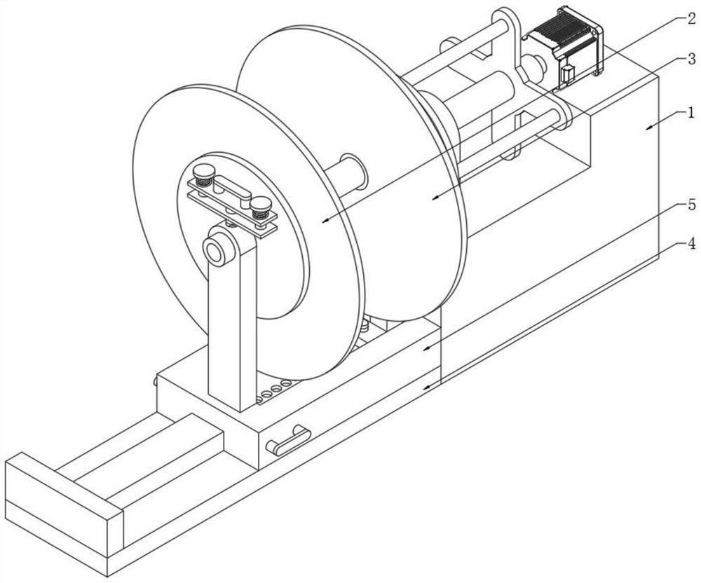
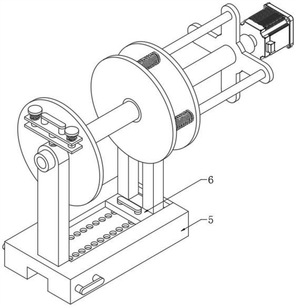
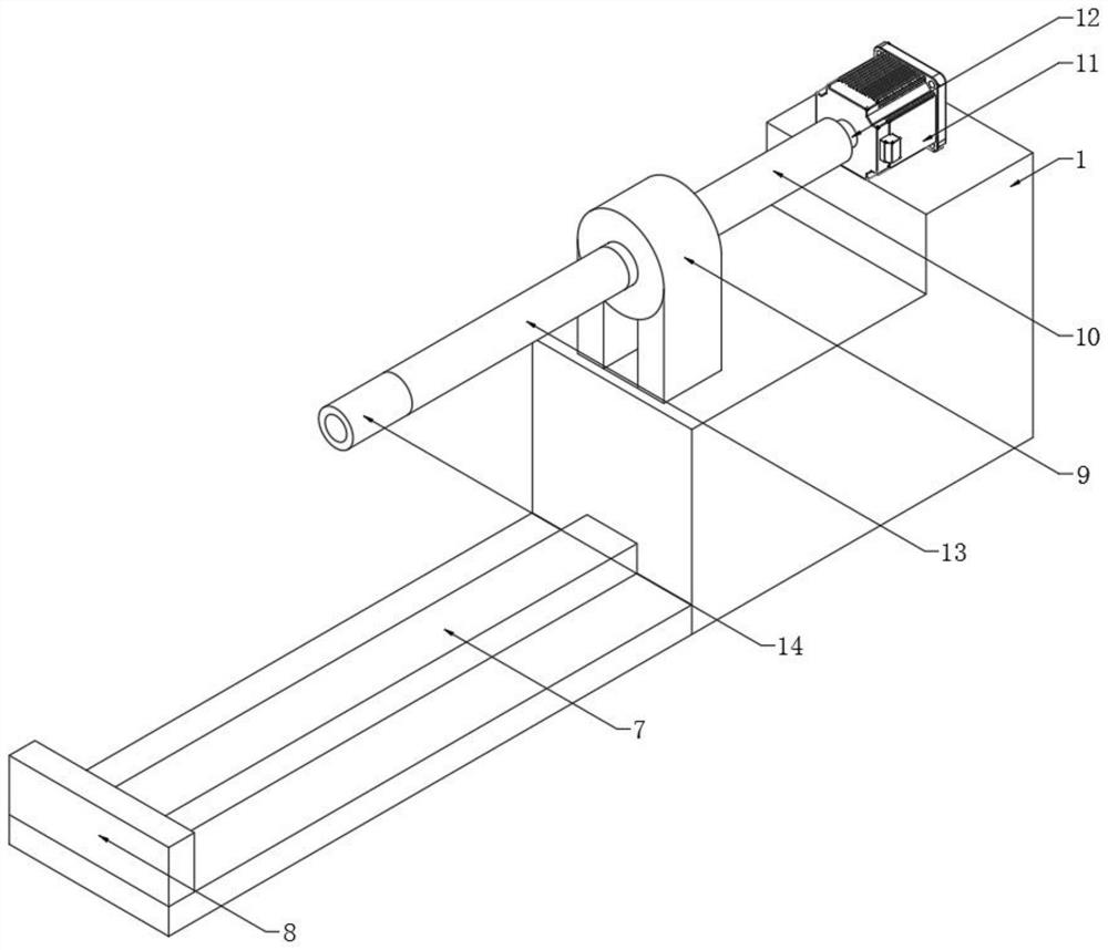
[0031] see Figure 1-7 , the present invention provides a technical solution: a high-precision alloy copper strip processing winding device provided with a guiding and correcting structure, including 1. a fixed frame; 2. a first deviation correcting disc; 3. a second deviation correcting disc; 4. Underframe; 5, positioning frame; 6, positioning plate; 7, slide rail; 8, baffle plate; 9, support seat; 10, first positioning sleeve; 11, motor; 12, positioning shaf...


PUM


Abstract

The invention discloses a high-precision alloy copper strip processing winding device with a guide deviation rectifying structure, which comprises a fixing frame, a bottom frame is fixedly arranged at one end of one side of the fixing frame, a sliding rail is fixedly arranged in the middle of the top of the bottom frame, a baffle is fixedly arranged at one end of the top of the bottom frame, and a positioning frame is slidably arranged at one end of the top of the sliding rail. Through extrusion of the other side of a copper strip inner supporting ring and one side of a second deviation rectifying disc, when a positioning strip is connected with a first positioning groove and a second positioning groove in a penetrating and inserting mode, a fixing strip is pressed downwards, so that the fixing strip is downwards inserted into a positioning hole in a sliding groove in a penetrating and inserting mode, and a motor fixed to the top of a fixing frame drives a positioning shaft to rotate; the positioning shaft drives the second positioning sleeve externally arranged in the middle and the copper strip inner supporting ring penetrating through the outer wall of the second positioning sleeve to rotate, so that the copper strip is stably wound, accurate deviation correction treatment is achieved in the winding process, and the winding efficiency of the copper strip winding device is improved.

Description

technical field [0001] The invention relates to the technical field, in particular to a winding device for high-precision alloy copper strip processing provided with a guiding and deviation-correcting structure. Background technique [0002] Copper strip is a kind of metal component. The product specifications are 0.1-3×50-250mm copper strip products in various states. It is mainly used for the production of electrical components, lamp holders, battery caps, buttons, seals, and connectors. It is mainly used for conductive, Heat conduction and corrosion resistant equipment. Such as electrical components, switches, gaskets, gaskets, electric vacuum devices, radiators, conductive base materials, and automotive water tanks, heat sinks, cylinder plates and other parts. [0003] Aiming at this, Chinese Patent No. CN110788162A proposes a kind of winding equipment for brass strip processing, by fixing the first guide rod and the second guide rod on both sides of the processing tabl...

Claims


Application Information

Patent Timeline
Patent Type & Authority Applications(China)
IPC IPC(8): B65H18/10B65H23/032B65H18/02
CPCB65H18/10B65H23/0322B65H18/02
Inventor 郑巨开
Owner JIANGXI TONGXIN COPPER IND
Features
  • Generate Ideas
  • Intellectual Property
  • Life Sciences
  • Materials
  • Tech Scout
  • Unparalleled Data Quality
  • Higher Quality Content
  • 60% Fewer Hallucinations
Learn More