
Fan and cleaning equipment

A fan and fan blade technology, applied in the field of fans and cleaning equipment, can solve the problems of high noise and inconvenient fan assembly, and achieve the effect of simple assembly

Pending Publication Date: 2022-03-15
BEIJING ROCKROBO TECH CO LTD
View PDF0 Cites 1 Cited by
  • Summary
  • Abstract
  • Description
  • Claims
  • Application Information

AI Technical Summary

Problems solved by technology

[0006] The purpose of the present invention is to provide a blower fan and a vacuum cleaner to solve the problems of inconvenient assembly and high noise of the blower fan in the prior art

Method used


Image

  • Fan and cleaning equipment
  • Fan and cleaning equipment
  • Fan and cleaning equipment

Examples


Embodiment Construction

[0035] In order to make the object, technical solution and advantages of the present invention clearer, the present invention will be further described in detail below in combination with specific embodiments and with reference to the accompanying drawings. It should be understood that these descriptions are exemplary only, and are not intended to limit the scope of the present invention. Also, in the following description, descriptions of well-known structures and techniques are omitted to avoid unnecessarily obscuring the concept of the present invention.

[0036] Apparently, the described embodiments are some, but not all, embodiments of the present invention. Based on the embodiments of the present invention, all other embodiments obtained by persons of ordinary skill in the art without making creative efforts belong to the protection scope of the present invention.

[0037] In addition, the technical features involved in the different embodiments of the present invention...


PUM


Abstract

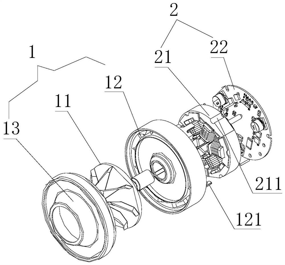
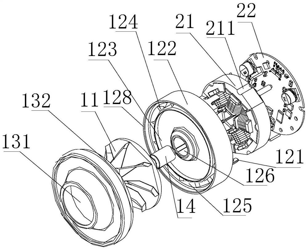
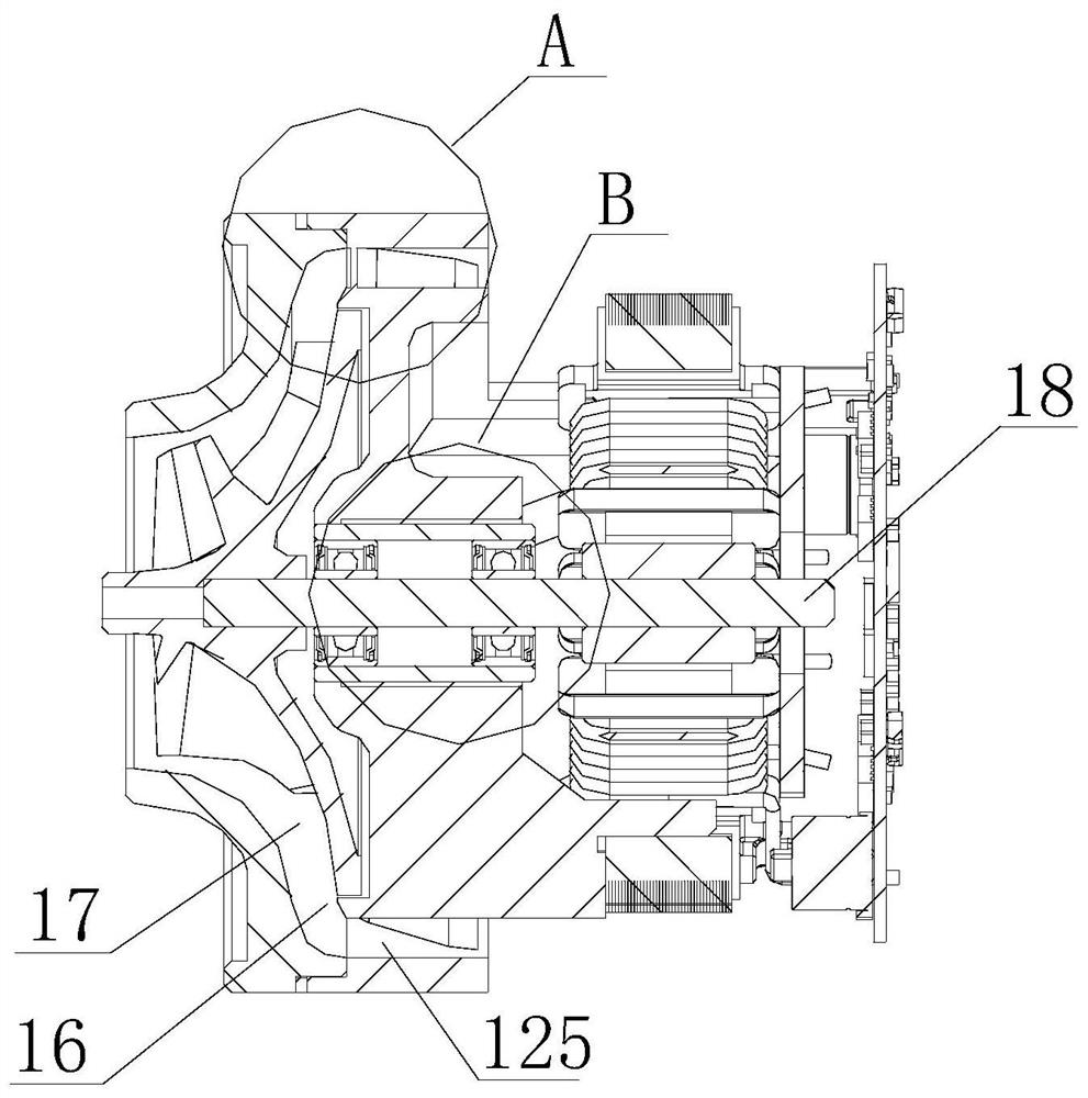
The invention discloses a draught fan and cleaning equipment, and the draught fan comprises a fluid module (1) used for generating airflow and guiding the airflow, the fluid module (1) comprises a diffuser (12), and the diffuser (12) is provided with a first positioning mechanism (121); and the stator module (2) is detachably connected with the diffuser (12), and the stator module (2) is provided with a second positioning mechanism (211) matched with the first positioning mechanism (121). The fan adopts a modular structure, is simple to assemble and is suitable for mechanical production.

Description

technical field [0001] The invention relates to the technical field of mechanical design, in particular to a fan and cleaning equipment. Background technique [0002] The fan is a machine that relies on the input mechanical energy to increase the gas pressure and discharge the gas. It is a driven fluid machine. Fan is the customary abbreviation for gas compression and gas conveying machinery in China. Generally speaking, fans include ventilators, blowers, and wind generators. [0003] Fans are mainly used in metallurgy, petrochemical, electric power, urban rail transit, textile, shipbuilding and other fields of national economy and ventilation in various places. In addition to traditional application fields, there will still be great development prospects in more than 20 potential market fields such as comprehensive utilization of coal gangue, technical transformation of new dry process clinker, energy saving in metallurgical industry, and comprehensive utilization of resou...

Claims


Application Information

Patent Timeline
Patent Type & Authority Applications(China)
IPC IPC(8): F04D25/08F04D29/64F04D29/54F04D29/66
CPCF04D25/0606F04D25/08F04D29/646F04D29/542F04D29/667F04D17/165F04D29/4253F04D29/444F04D29/059F04D25/06F04D25/0693A47L9/22H02K7/14H02K1/148H02K3/28F04D29/626A47L5/22A47L9/0081
Inventor 李长城李行
Owner BEIJING ROCKROBO TECH CO LTD
Learn More