High-uniformity CCM continuous coating process for fuel cell

A fuel cell and coating technology, used in fuel cells, battery electrodes, devices for coating liquids on surfaces, etc. performance and service life, improved coating uniformity, and the effect of improving coating uniformity

Pending Publication Date: 2022-03-18
DALIAN INST OF CHEM PHYSICS CHINESE ACAD OF SCI
View PDF0 Cites 2 Cited by
  • Summary
  • Abstract
  • Description
  • Claims
  • Application Information

AI Technical Summary

Problems solved by technology

[0003] On the other hand, in the CCM preparation process, the catalyst slurry itself has a certain fluidity. After it is coated on the proton exchange membrane, there will be a microscopic flow phenomenon during the continuous transmission of the membrane. At this time, the It will affect the uniformity of the coating surface; in order to reduce the flow of the slurry, the concentration of the slurry can be increased when preparing the catalyst slurry, but the slurry with a higher concentration, due to its poor fluidity and high surface tension , so there are still many particles after the slurry is stirred, and combined with the problem of weak adhesion of the slurry on the surface of the proton membrane, it leads to uniformity problems such as particles, pinholes, and defects on the final CCM surface, which directly affects the CCM pass rate
[0004] In order to solve the above problems in the prior art, most of them use CCM for preparing thin-layer coatings or adopt multiple coating processes combined with CCD detection equipment to improve the pass rate of CCM, but thin-layer coatings do not meet the actual performance requirements, and multiple coatings Although the method of coating can improve the uniformity problem, problems such as film swelling and catalytic layer cracks during each coating are also technical problems in the existing field, and the subsequent use of CCD detection can only improve the pass rate of the final product, but cannot reduce The failure rate will eventually lead to a certain degree of waste

Method used

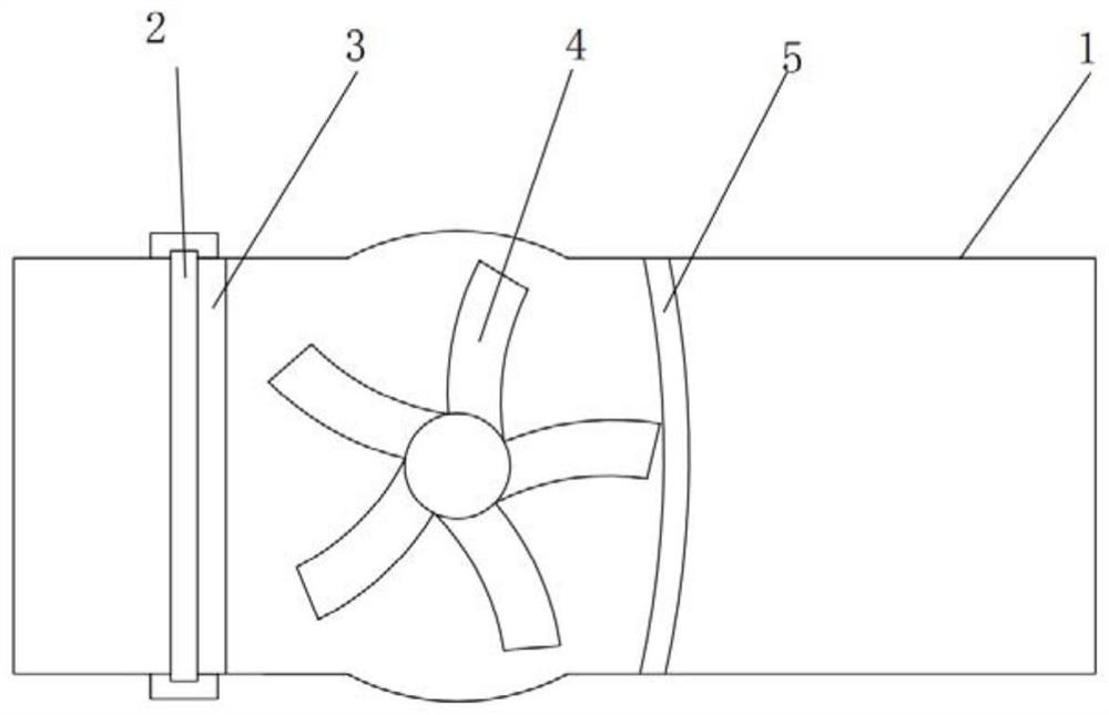
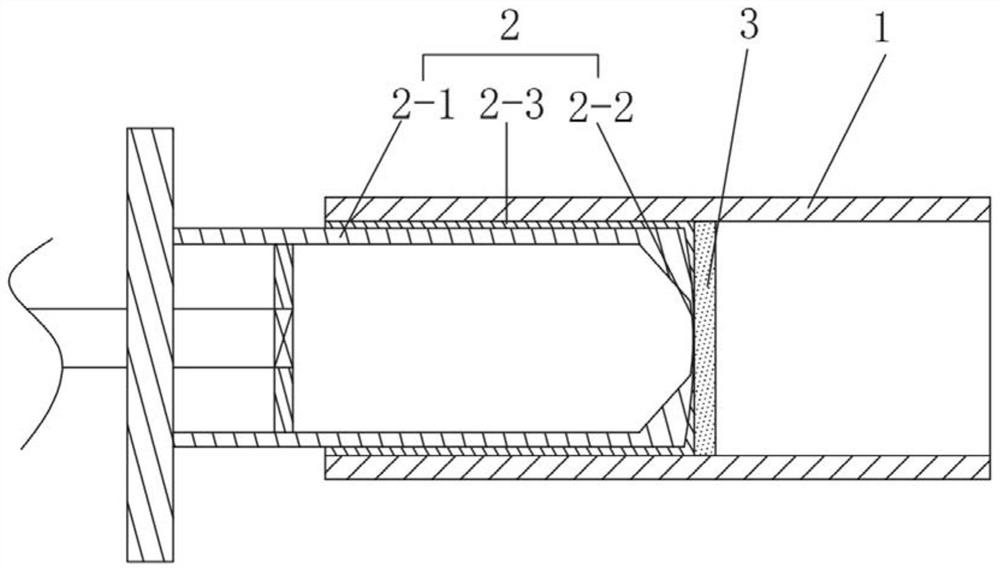

Image

  • High-uniformity CCM continuous coating process for fuel cell
  • High-uniformity CCM continuous coating process for fuel cell
  • High-uniformity CCM continuous coating process for fuel cell

Examples


Embodiment 1

[0034] A fuel cell CCM preparation process, comprising the following steps:

[0035] (1) prepare low-concentration catalyst slurry: take by weighing 20g 70% Pt / C catalyst, 100g 10% perfluorosulfonic acid resin solution and 800g isopropanol, mix, high-speed stirring disperses, adopts vacuum defoaming to make low Concentration catalyst slurry;

[0036] (2) Preparation of high-concentration catalyst slurry: Weigh 20g of 70% Pt / C catalyst, 100g of 10% perfluorosulfonic acid resin solution, 40g of ethylene glycol and 600g of isopropanol, mix, stir at high speed to disperse, and use vacuum Defoaming to prepare high-concentration catalyst slurry;

[0037] (3) Use roll-to-roll coating equipment to place the anode low-concentration catalyst slurry and the cathode high-concentration catalyst slurry in the anode feed system and the cathode feed system, respectively;

[0038] (4) Coating the low-concentration catalyst slurry in step (1) on the A side of the proton exchange membrane by a...

Embodiment 2

[0040] (1) prepare low-concentration catalyst slurry: take by weighing 20g 40% Pt / C catalyst, 200g 5% perfluorosulfonic acid resin solution and 2000g isopropanol, mix, high-speed stirring disperses, adopts vacuum defoaming to make low Concentration catalyst slurry;

[0041] (2) Prepare high-concentration catalyst slurry: take by weighing 20g of 40% Pt / C catalyst, 200g of 5% perfluorosulfonic acid resin solution, 120g of glycerol and 1000g of isopropanol, mix, stir at high speed to disperse, and use vacuum Defoaming to prepare high-concentration catalyst slurry;

[0042] (3) Use roll-to-roll coating equipment to place the anode low-concentration catalyst slurry and the cathode high-concentration catalyst slurry in the anode feed system and the cathode feed system, respectively;

[0043] (4) The low-concentration catalyst slurry in step (1) is coated on the A side of the proton exchange membrane by adopting the process parameters of coating speed 5m / min and coating wet thicknes...

Embodiment 3

[0045] (1) prepare low-concentration catalyst slurry: take by weighing 20g 60% Pt / C catalyst, 120g 5% perfluorosulfonic acid resin solution and 1800g isopropanol, mix, high-speed stirring disperses, adopts vacuum defoaming to make low Concentration catalyst slurry;

[0046] (2) Preparation of high-concentration catalyst slurry: Weigh 20g of 60% Pt / C catalyst, 160g of 5% perfluorosulfonic acid resin solution, 80g of ethyl acetate and 800g of isopropanol, mix, stir at high speed to disperse, and use vacuum Defoaming to prepare high-concentration catalyst slurry;

[0047] (3) Use roll-to-roll coating equipment to place the anode low-concentration catalyst slurry and the cathode high-concentration catalyst slurry in the anode feed system and the cathode feed system, respectively;

[0048] (4) Coating the low-concentration catalyst slurry in step (1) on the A side of the proton exchange membrane by adopting the technological parameters of coating speed 8m / min and coating wet thick...


PUM


Abstract

The invention discloses a fuel cell CCM preparation process, which comprises the following steps: respectively preparing anode low-concentration catalyst slurry and cathode high-concentration catalyst slurry, coating the low-concentration catalyst slurry on the A surface of a proton exchange membrane, drying to prepare the anode side of the CCM, coating the high-concentration catalyst slurry on the B surface of the proton exchange membrane, and drying to prepare the cathode side of the CCM. And drying to serve as a cathode side, and finally preparing the CCM with the distinguishable cathode and anode. Wherein the drying mode for the low-concentration catalyst slurry is that the low-concentration catalyst slurry firstly enters a drying tunnel to be in a gel state and then is subjected to hot pressing; the drying mode for the high-concentration catalyst slurry is tunnel drying; the CCM cathode and the CCM anode can be distinguished, and meanwhile, the uniformity of the CCM coating is relatively improved, so that the percent of pass is increased, and the waste phenomenon is reduced.

Description

technical field [0001] The invention relates to the field of fuel cells, in particular to a high-uniformity CCM continuous coating process for fuel cells. Background technique [0002] Fuel cell CCM is one of the important components of fuel cells. The main process is to coat the catalyst slurry on the proton exchange membrane and form CCM after drying. In the existing CCM preparation process, its surface uniformity has always been a key research and development technology in this field. One, at the same time, for the cathode and anode of CCM, in this field, the cathode and anode are mostly distinguished by the level of loading, that is, the one with high loading is the cathode side, and the one with low loading is the anode side. However, in the preparation process of CCM, the loading It is difficult to control the amount of high and low. Since the slurry loading on both sides of the CCM is required to be different, the slurry needs to be strictly regulated in terms of the ...

Claims


Application Information

Patent Timeline
Patent Type & Authority Applications(China)
IPC IPC(8): H01M4/88H01M8/1004B01D29/03B01D29/76B05D7/04B05D7/24
CPCH01M4/8828H01M4/8882H01M8/1004B05D7/04B05D7/24B01D29/035B01D29/76Y02E60/50
Inventor 郝金凯张洪杰邵志刚
Owner DALIAN INST OF CHEM PHYSICS CHINESE ACAD OF SCI
Why Eureka
Try Eureka