Industrial model manufacturing device
A technology for making devices and models, applied in the direction of manufacturing tools, grinding workpiece supports, metal processing equipment, etc., to achieve the effect of improving safety, simple and convenient use and operation, and improving efficiency and speed
- Summary
- Abstract
- Description
- Claims
- Application Information
AI Technical Summary
Problems solved by technology
Method used
Image
Examples
Embodiment 1
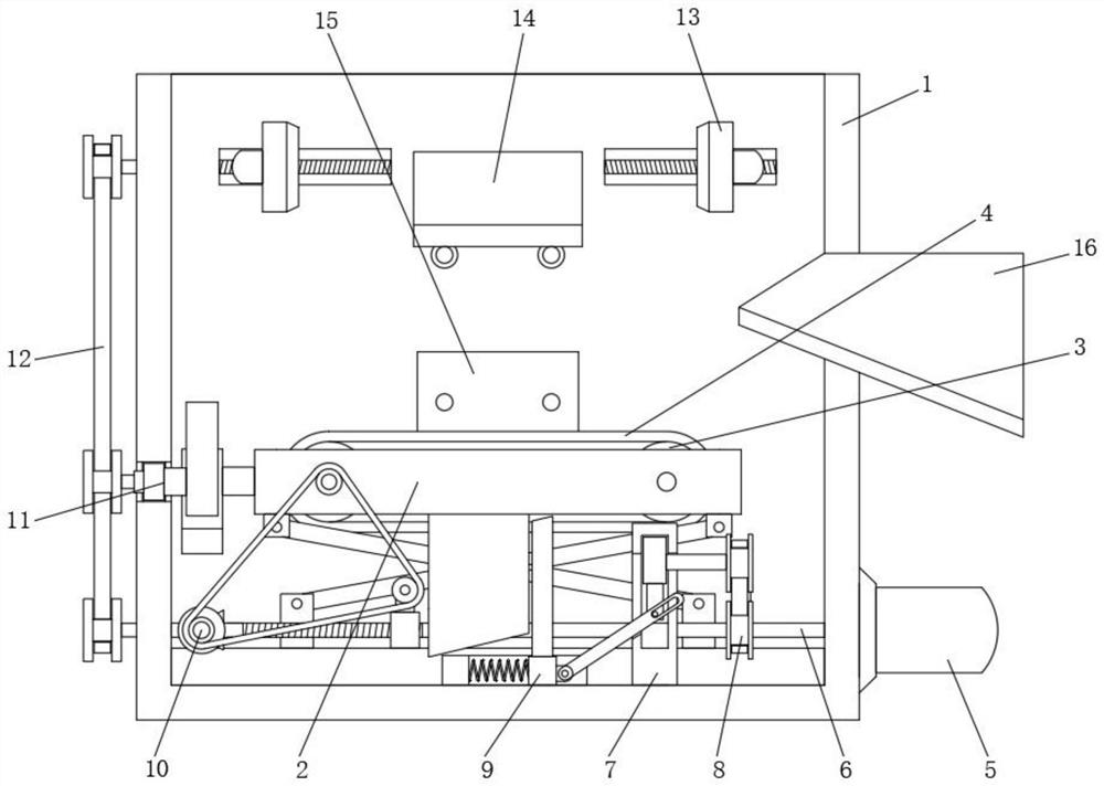
[0036] Embodiment one, by Figure 1 to Figure 8 Given, the present invention comprises equipment casing 1, and the interior of equipment casing 1 is provided with lifting U-shaped frame 2, and the inside of lifting U-shaped frame 2 is equipped with two turning rollers 3, and the surface of two turning rollers 3 is installed There is a grinding belt 4, two motors 5 are installed on the bottom of one side of the equipment housing 1, and a main rotating shaft 6 is installed on one side of the inner bottom of the equipment housing 1, and the output end of one of the motors 5 is connected to the main rotating shaft 6 A second transmission mechanism 10 is installed between one side of the main rotating shaft 6 and the lifting U-shaped frame 2 and the inner wall of the equipment casing 1, and a second transmission mechanism 10 is installed between the other side of the equipment casing 1 and the lifting U-shaped frame 2. Two control mechanisms 11, one end of the main rotating shaft 6...
Embodiment 2
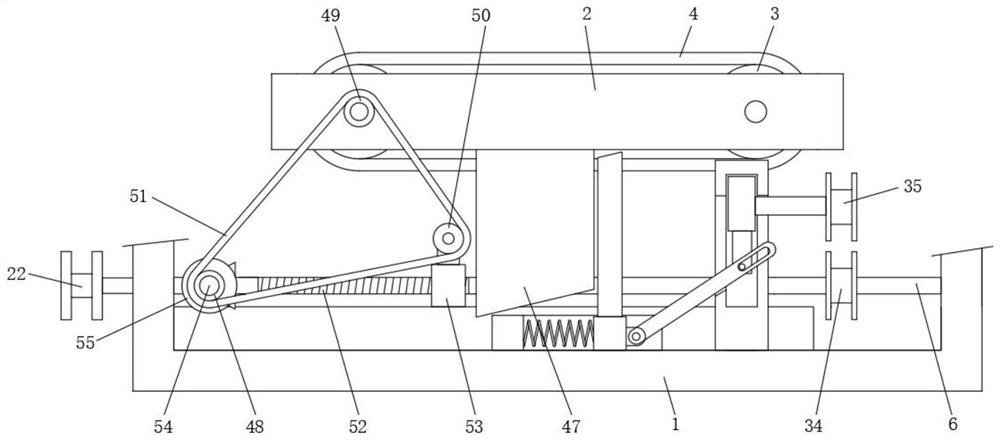
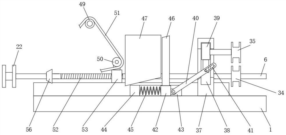
[0041] Embodiment two, on the basis of embodiment one, by Figure 3 to Figure 5 Given, the bottom of the equipment housing 1 is installed with a first fixing assembly 7, a first transmission mechanism 8 is installed between one side of the first fixing assembly 7, the main rotating shaft 6 and the lifting U-shaped frame 2, and the first fixing A first control mechanism 9 is installed between the other side of the assembly 7 and the lifting U-shaped frame 2; a second two-way threaded rod 30 is installed in the middle of the bottom of the equipment housing 1, wherein another motor 5 is connected to the second two-way threaded rod 30 connection, both sides of the second two-way threaded rod 30 are equipped with a threaded moving bar 31, and an extruding adjusting rod 32 is installed between the two ends of the threaded moving bar 31 and the bottom of the lifting U-shaped frame 2, thereby effectively The lifting U-shaped frame 2 is adjusted for lifting; the first transmission mech...
Embodiment 3
[0045] Embodiment three, on the basis of embodiment one, by figure 2 , image 3 and Figure 8 Given, the second transmission mechanism 10 includes a rotating pin 54, the rotating pin 54 is installed at the bottom of the device housing 1, the first gear 48 and the first bevel gear 55 are installed on one side of the rotating pin 54, the main rotating shaft 6 One side is provided with threaded section 52, and one side of main rotating shaft 6 is connected with threaded moving block 53 by threaded section 52, and the top of threaded moving block 53 is equipped with second gear 50, and one side of lifting U-shaped frame 2 is installed with the first Three gears 49, the third gear 49 is connected with one end of one of the rotating rollers 3, a transmission chain 51 is installed between the third gear 49 and the first gear 48 and the second gear 50, and the first side of the main rotating shaft 6 is installed Two bevel gears 56, the second bevel gear 56 is meshed with the first ...
PUM
 Abstract
Description
Claims
Application Information
 - R&D
- Intellectual Property
- Life Sciences
- Materials
- Tech Scout
- Unparalleled Data Quality
- Higher Quality Content
- 60% Fewer Hallucinations
Browse by: Latest US Patents, China's latest patents, Technical Efficacy Thesaurus, Application Domain, Technology Topic, Popular Technical Reports.
© 2025 PatSnap. All rights reserved.Legal|Privacy policy|Modern Slavery Act Transparency Statement|Sitemap|About US| Contact US: help@patsnap.com


