Waste heat recycling device

A waste heat recovery and heat exchanger technology, applied in the field of boiler recovery, can solve problems such as unguaranteed production, reduced boiler service life, and shortened boiler service life, so as to achieve the effects of saving natural gas energy, saving production costs, and improving utilization efficiency

Pending Publication Date: 2022-03-22
GUILIN PHARMA
View PDF0 Cites 0 Cited by
  • Summary
  • Abstract
  • Description
  • Claims
  • Application Information

AI Technical Summary

Problems solved by technology

[0002] At present, a large amount of condensed water will be produced after the combustion of gas-fired boilers. If the condensed water is discharged directly, it will cause energy waste. At the same time, due to the high calorific value of condensed water, it will cause great damage and pollution to the environment, and it will not It is beneficial to the protection of the environment, and it is also a waste of thermal energy; if the condensation technology is recycled as soft water for steam production, after testing, if the water quality does not meet the boiler water requirements, it will affect the boiler body and shorten the service life of the boiler. , and according to the characteristics of unstable water quality, unstable pH, and high hardness of condensed water, if the condensed water is directly used as soft water to generate steam, in the case of unstable water quality, it is not conducive to continuous steam production, and production cannot be guaranteed; when the pH is unstable In the case of high hardness, it is easy to corrode the boiler wall and pipes, causing damage to the boiler and reducing the service life of the boiler; in the case of high hardness, it does not meet the national steam soft water standard, and the steam produced cannot meet the production standard, affecting the product and the boiler is easy Scaling requires frequent cleaning of the boiler to generate cleaning fees, which is not conducive to the long-term efficiency and practicality of the boiler

Method used


Image

  • Waste heat recycling device

Examples


Embodiment Construction

[0038] The principles and features of the present invention are described below in conjunction with the accompanying drawings, and the examples given are only used to explain the present invention, and are not intended to limit the scope of the present invention.

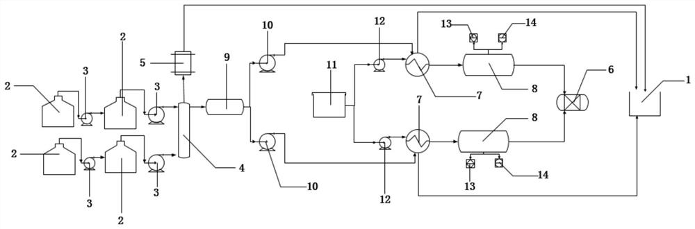
[0039] Such as figure 1 As shown, a waste heat recovery and utilization device includes a condensed water input assembly, a steam-water separation component for steam-water separation of condensed water, a steam processing component for processing the separated steam, and a steam-water separation component for separating the separated condensate Water is treated by condensate treatment components and sewage station 1,

[0040] The condensed water input assembly is connected to the steam-water separation component, the steam processing component is respectively connected to the steam-water separation component and the sewage station 1, and the condensed water treatment component is respectively connected to the steam...


PUM


Abstract

The invention provides a waste heat recycling device. The waste heat recycling device comprises a condensate water input assembly, a steam-water separation component, a steam treatment component, a condensate water treatment assembly and a sewage station, wherein the steam-water separation component is used for carrying out steam-water separation on condensate water; the steam treatment component is used for treating separated steam; the steam generation amount is reduced, so that the use amount of natural gas is reduced, natural gas energy is saved, secondary utilization of condensate water is achieved through the condensate water treatment assembly and the sewage station, the service life of the boiler is prolonged, the exhaust gas temperature of the boiler is reduced, the steam production gas-steam ratio is increased, and the steam production cost is saved; the energy utilization efficiency is effectively improved, great economic benefits are generated, and the purpose of recycling condensate water is achieved.

Description

technical field [0001] The invention mainly relates to the technical field of boiler recovery, in particular to a waste heat recovery and utilization device. Background technique [0002] At present, a large amount of condensed water will be produced after the combustion of gas-fired boilers. If the condensed water is discharged directly, it will cause energy waste. At the same time, due to the high calorific value of condensed water, it will cause great damage and pollution to the environment, and it will not It is beneficial to the protection of the environment, and it is also a waste of thermal energy; if the condensation technology is recycled as soft water for steam production, after testing, if the water quality does not meet the boiler water requirements, it will affect the boiler body and shorten the service life of the boiler. , and according to the characteristics of unstable water quality, unstable pH, and high hardness of condensed water, if the condensed water i...

Claims


Application Information

Patent Timeline
IPC IPC(8): F22D11/06F22D1/00F24D17/00
CPCF22D11/06F22D1/00F24D17/0005F24D2200/16Y02B30/18
Inventor 王建军杨晓刘畅刘辉廖军王姗姗谢伟军谢龙军杨文彪蒲兰涛
Owner GUILIN PHARMA
Why Eureka
Try Eureka