Heating sorting equipment used in process of detecting asphalt content by combustion method

A technology of asphalt content and combustion method, which is applied in chemical analysis by combustion and weighing by removing certain components, can solve the problems of difficulty in estimating correction coefficients and complex labor costs, and achieves good human-computer interaction performance and improvement. Product quality, the effect of low labor intensity of workers

Pending Publication Date: 2022-03-22
李靖
View PDF7 Cites 0 Cited by
  • Summary
  • Abstract
  • Description
  • Claims
  • Application Information

AI Technical Summary

Problems solved by technology

[0007] The purpose of the present invention is to solve the difficulty in estimating the c...

Method used


Image

  • Heating sorting equipment used in process of detecting asphalt content by combustion method
  • Heating sorting equipment used in process of detecting asphalt content by combustion method
  • Heating sorting equipment used in process of detecting asphalt content by combustion method

Examples


Embodiment 1

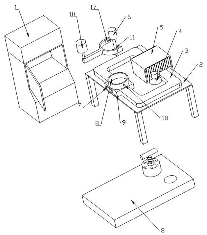
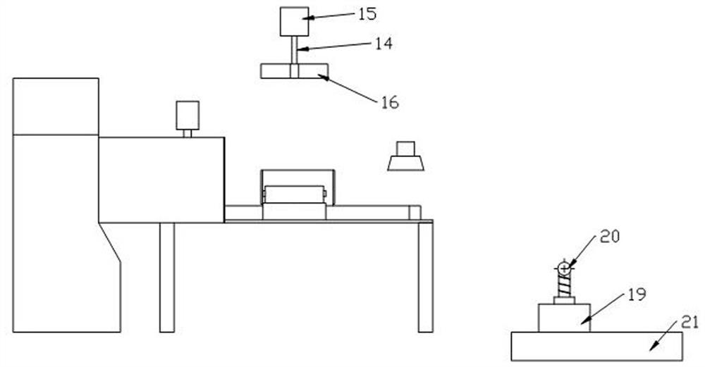
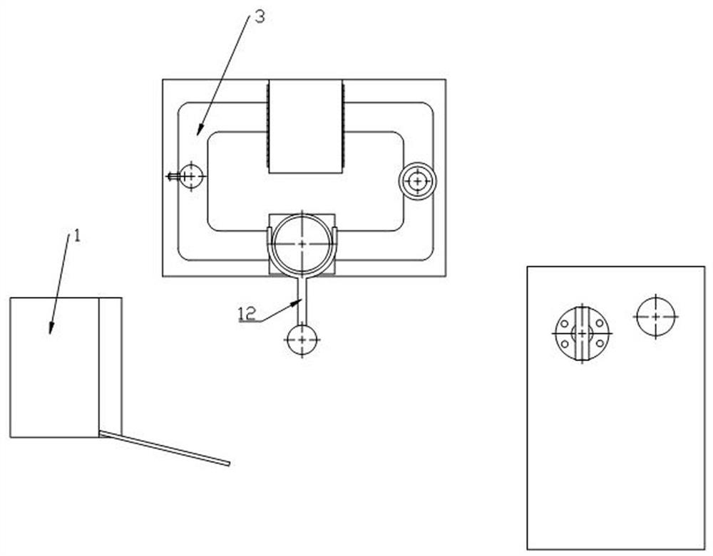
[0028] A kind of heating sorting equipment used in the process of detecting bitumen content by combustion method, see Figure 1 to Figure 4 , the design includes an asphalt detection furnace for the combustion method, the discharge port of the hoisting mechanism 10 is at the entrance of the asphalt detection furnace, the material inlet of the hoisting mechanism 10 is at the outlet of the pilot detection device, and the pilot detection device includes a feeding platform 2, a feeding platform 2 It is equipped with a word-shaped assembly line 3 and a power element that drives the assembly line 3 to run. Along the assembly line 3, a drying mechanism 4, a heating mechanism 5, a smoothing mechanism 6, an inspection mechanism, and a test block platform 9 are arranged in sequence. The table 9 includes a square platform and a cylindrical test block basket 8 installed on the square platform. Positioning columns 18 are arranged on both sides of the test block basket 8 , and a screw connec...

Embodiment 2

[0038]The working principle of this embodiment is the same as that of Embodiment 1, the specific difference is that the pilot detection device is replaced by a feeding platform 2, and a mouth-shaped assembly line 3 is arranged on the feeding platform 2 along the direction of the assembly line 3. Drying mechanism 4, heating mechanism 5, smoothing mechanism 6 and inspection mechanism, each side of the heating mechanism 5 is provided with a test block platform 9, and the test block platform 9 includes a square platform and a cylindrical test block installed on the square platform Basket 8 and positioning columns 18 are arranged on both sides of the test block basket 8, and a backing plate for transitional placement of the cylindrical test block basket 8 is provided in the heating mechanism 5.

[0039] In this embodiment, the assembly line 3 includes a plurality of sliding rollers, the sliding rollers themselves are not connected to the power mechanism, and the movement of the test...


PUM


Abstract

The invention relates to the field of asphalt detection equipment, in particular to heating and sorting equipment used in the process of detecting the asphalt content through a combustion method. The invention aims to improve the asphalt content detection efficiency and the precision of the detection result at the present stage. The device comprises an asphalt detection furnace, a discharge port of a hoisting mechanism is located at an inlet of the asphalt detection furnace, the inlet is located at an outlet of a pilot detection device, the pilot detection device comprises a feeding platform, and the feeding platform is provided with a square assembly line and a power element for driving the assembly line to operate. A drying mechanism, a heating mechanism, a uniform smearing mechanism and an observation mechanism through which a test block table can pass are sequentially arranged along the direction of the assembly line, and the test block table comprises a square platform and a cylindrical test block basket mounted on the square platform. The method has the advantages that the pilot step is preset in front of the detection furnace, so that a more accurate detection result and higher detection efficiency are provided.

Description

technical field [0001] The invention relates to the field of asphalt detection equipment, in particular to heating and sorting equipment used in the process of detecting asphalt content by combustion method. Background technique [0002] Combustion method to measure asphalt binder content in hot mix asphalt mixture is to put the hot mix asphalt mixture into a combustion furnace at 538 ℃, and the asphalt binder is burned. The bitumen content in the mixture can be calculated according to the mass difference of the mixture before and after combustion. [0003] During the combustion test, some mass (usually less than 0.4%) is usually lost for most mineral materials. The measured mass loss of the hot mix asphalt mixture during the combustion test consists of the mass loss of the asphalt binder and the mass loss of the aggregate. The mass loss of the asphalt binder is obtained by subtracting the mass loss of the aggregate from the measured total mass loss. According to the mass...

Claims


Application Information

Patent Timeline
IPC IPC(8): G01N5/04G01N31/12
CPCG01N5/04G01N31/12
Inventor 李靖张跃立
Owner 李靖
Why Eureka
Try Eureka