PFC coil device and use method

A technology of coil device and wire plate, which is applied in the direction of transformer/inductor coil/winding/connection, transformer/reactor installation/support/suspension, high-efficiency power electronic conversion, etc., which can solve the problem that the manual winding force is difficult to control and consumes a lot of money Problems such as labor and time, automatic winding of magnetic cores, etc., achieve the effect of facilitating automatic winding, saving costs, and avoiding coil scattering

Active Publication Date: 2022-03-22
江苏威科变压器有限公司
View PDF5 Cites 0 Cited by
  • Summary
  • Abstract
  • Description
  • Claims
  • Application Information

AI Technical Summary

Problems solved by technology

[0004] At present, when winding the magnetic core in the PFC coil device, it is first necessary to inject the winding skeleton into the shape of the magnetic core, and then carry out integral winding. Since there are many shapes of the magnetic core, it is impossible to use all magnetic cores. For example, when winding a U-shaped magnetic core, manual winding is required to ensure the neatness of the winding, but the strength of manual winding is not easy to control, resulting in unstable winding structure and costly A lot of labor and time, and the existing PFC uses epoxy resin or adhesive tape to assemble the upper and lower magnetic cores. The manufacturing process is complicated. Although the wrapping is good, the heat dissipation is not good.

Method used


Image

  • PFC coil device and use method
  • PFC coil device and use method
  • PFC coil device and use method

Examples


Embodiment 1

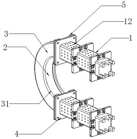
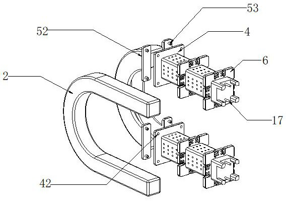
[0047] A PFC coil device, see Figure 1-Figure 6The present invention mainly includes a cuboid winding skeleton 1, a U-shaped magnetic core 2 and an arc-shaped casing 3. In this embodiment, the U-shaped magnetic core 2 is a high-permeability core with small impedance deviation and large output current. High inductance, can suppress high-order harmonics and other characteristics, widely used in electronic equipment such as color TVs, computers, monitors, etc., the number of winding bobbins 1 is two and is wound with wires, and one end of the winding bobbin 1 is provided with a slot 11. The two ends of the U-shaped magnetic core 2 are respectively movably inserted inside the two slots 11. The U-shaped magnetic core 2 matches the size of the slot 11, which can prevent the U-shaped magnetic core 2 from loosening and shaking. Affecting the inductance efficiency, the outer peripheral side of one end of the winding frame 1 is fixedly provided with a mounting plate 4, the cross-sectio...

Embodiment 2

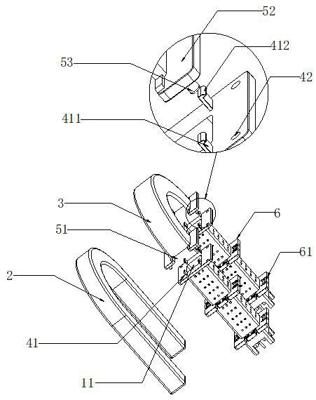
[0057] A PFC coil device, see Figure 1-Figure 9 In the present embodiment, mainly comprise the winding frame 1 of cuboid, I property magnetic core 7, the quantity of winding frame 1 is one and is wound with coil 13, and one end of winding frame 1 offers slot 11, 1 One end of the magnetic core 7 is movably inserted inside the slot 11, and the I magnetic core 7 is adapted to the size of the slot 11, which can prevent the I magnetic core 7 from loosening, shaking, and affecting the inductance efficiency. 1. The fixed sleeve on the outer peripheral side of one end is provided with a mounting plate 4. The cross-sectional area of ​​the mounting plate 4 is larger than the cross-sectional area of ​​the winding skeleton 1. A block 41 is installed on the mounting plate 4. The movable cover is on the opening side of the mounting plate 4. A cover plate 43 is provided, and the block 41 includes an elastic plate 411 vertically fixed on the mounting plate 4. The elastic plate 411 is an elas...

Embodiment 3

[0063] A method for using a PFC coil device, comprising:

[0064] The rectangular parallelepiped winding frame 1 and the arc-shaped casing 3 are formed by injection molding. It should be noted that the mounting plate 4, two wire plates 6, the fixing block 15, the fixing feet 16 and the winding frame 1 are integrally injected, and the clamping plate 5 It is integrally injected with the arc-shaped casing 3, and injection molding is a method for producing and modeling industrial products;

[0065] The wire end 14 on the coil 13 is guided and positioned through the wire groove 61 on the wire plate 6 and the coil 13 is wound on the winding frame 1. According to the application scene of the device, coils 13 with different numbers of turns are selected;

[0066] Select a U-shaped magnetic core 2 with a suitable magnetic permeability, insert the two ends of the U-shaped magnetic core 2 into the slots 11 of the two winding bobbins 1, and set the socket 31 of the arc-shaped casing 3 in ...


PUM


Abstract

The invention discloses a PFC coil device, and relates to the technical field of PFC coil devices. The transformer mainly comprises winding frameworks, a U-shaped magnetic core and an arc-shaped sleeve shell, the number of the winding frameworks is two, wires are wound around the winding frameworks, slots are formed in one ends of the winding frameworks, the two ends of the U-shaped magnetic core are movably inserted into the two slots respectively, the peripheral side of one end of each winding framework is sleeved with a mounting plate, and the mounting plates are movably inserted into the slots respectively. A mounting plate is arranged on the U-shaped magnetic core, a clamping block is mounted on the mounting plate, a plurality of uniformly distributed heat dissipation holes are formed in the winding framework in a penetrating manner, an insertion opening extending along the track of the inner side of the arc-shaped sleeve shell is formed in the inner side of the arc-shaped sleeve shell, the arc-shaped sleeve shell movably sleeves the U-shaped magnetic core, and clamping plates fixedly sleeve the peripheral sides of the two ends of the arc-shaped sleeve shell. And a clamping groove is formed in the clamping plate. Automatic coil winding can be achieved, efficiency is improved, stability is high, labor cost is saved, meanwhile, heat dissipation is facilitated, and normal use is not affected.

Description

technical field [0001] The invention relates to the technical field of PFC coil devices, in particular to a PFC coil device and a use method. Background technique [0002] PFC means "power factor correction". Power factor refers to the relationship between effective power and total power consumption (apparent power), that is, the ratio of effective power divided by total power consumption (apparent power). Basically, the power factor can measure the degree to which electricity is effectively utilized. When the value of the power factor is larger, it means that the power utilization rate is higher. Power factor is a parameter used to measure the power efficiency of electrical equipment, and low power factor represents low power efficiency. The technology to improve the power factor of electrical equipment is called power factor correction. [0003] There are two types of PFC at present, one is passive PFC (also called passive PFC) and active PFC (also called active PFC). P...

Claims


Application Information

Patent Timeline
Patent Type & Authority Applications(China)
IPC IPC(8): H01F27/06H01F27/08H01F27/26H01F27/28H01F27/30H01F41/00
CPCH01F27/306H01F27/266H01F27/2876H01F27/08H01F27/06H01F27/2828H01F41/00H01F2027/065Y02B70/10
Inventor 郭寿鹏
Owner 江苏威科变压器有限公司
Why Eureka
Try Eureka