Hydrogen circulating system of fuel cell system

A fuel cell system and circulation system technology, which is applied to fuel cells, fuel cell additives, electrical components, etc., can solve the difficulty of further reducing the humidity of circulating hydrogen, aggravating the difficulty of draining the anode side of the fuel cell, and increasing the power consumption of the fuel cell system, etc. problems, to simplify the control of the hydrogen circulation system, reduce the risk of flooding, and take up less space.

Pending Publication Date: 2022-03-22
上海澄朴科技有限公司
View PDF0 Cites 1 Cited by
  • Summary
  • Abstract
  • Description
  • Claims
  • Application Information

AI Technical Summary

Problems solved by technology

In the limited space of a highly integrated fuel cell system, it is impossible to design a large and complex gas-water separation device, so it is difficult to guarantee the separation efficiency of liquid water
Moreover, there is condensation after the circulating hydrogen gas with high temperature and saturated humidity is mixed with low temperature dry hydrogen gas, which also aggravates the difficulty of draining water on the anode side of the fuel cell.
Existing technology is difficult to further reduce the humidity in circulating hydrogen
If the traditional condensation method is used to dehumidify, the hydrogen needs to be heated after cooling down, which makes the system very complicated and increases the power consumption inside the fuel cell system

Method used


Image

  • Hydrogen circulating system of fuel cell system

Examples


Embodiment Construction

[0021] The present invention will be described in detail below in conjunction with the accompanying drawings and specific embodiments. This embodiment is carried out on the premise of the technical solution of the present invention, and detailed implementation and specific operation process are given, but the protection scope of the present invention is not limited to the following embodiments.

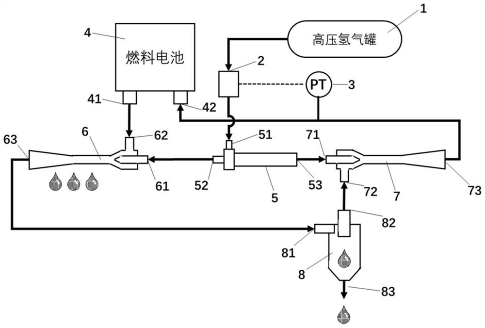
[0022] A fuel cell system hydrogen circulation system, such as figure 1 As shown, it includes a hydrogen source 1, a valve group 2, a vortex tube 5, a first ejector 6, a second ejector 7 and a gas-water separator 8, as well as connecting pipes and various sensors;

[0023] The output end of the hydrogen source 1 is connected to the vortex tube 5 through the valve group 2, specifically the inlet 51 of the vortex tube, the cold end outlet 52 of the vortex tube is connected to the jet inlet 61 of the first ejector, and the hot end outlet of the vortex tube 53 is connected to the jet inl...


PUM


Abstract

The invention relates to a hydrogen circulation system of a fuel cell system, which comprises a hydrogen source, a valve group, a vortex tube, a first ejector, a second ejector and a gas-water separator, the output end of the hydrogen source is connected to the input end of the vortex tube through the valve group, and the cold end outlet of the vortex tube is connected to the jet inlet of the first ejector. The hot end outlet is connected to the jet flow inlet of the second ejector, the drainage inlet of the first ejector is connected to the hydrogen outlet of the fuel cell, the outlet of the first ejector is connected to the inlet of the gas-water separator, the gas outlet of the gas-water separator is connected to the drainage inlet of the second ejector, and the outlet of the second ejector is connected to the hydrogen inlet of the fuel cell. Compared with the prior art, the water environment of the anode side of the fuel cell can be improved, the performance of the fuel cell is improved, the service life of the fuel cell is prolonged, the control of a hydrogen circulation system is simplified, the operation reliability is improved, the size is reduced, and the power density of the fuel cell system is improved.

Description

technical field [0001] The invention relates to a hydrogen circulation system, in particular to a hydrogen circulation system of a fuel cell system. Background technique [0002] A fuel cell is a power generation device that directly converts the chemical energy of fuel into electrical energy. The fuel cell system has high energy conversion efficiency and is an ideal energy utilization method. There is a broad prospect for commercial application. In practice, in order to avoid problems such as power generation performance degradation caused by low reaction gas concentration and water flooding caused by reduced gas flow, the supply of hydrogen and oxygen to the fuel cell must be higher than the amount consumed by the electrochemical reaction. In order to improve the utilization rate of hydrogen and at the same time carry out effective water management for fuel cells, hydrogen recycling is a very effective method. Generally, two methods are used for the hydrogen circulation o...

Claims


Application Information

Patent Timeline
Patent Type & Authority Applications(China)
IPC IPC(8): H01M8/04119H01M8/04082H01M8/04291
CPCH01M8/04201H01M8/04164H01M8/04291Y02E60/50
Inventor 袁昆马天才
Owner 上海澄朴科技有限公司
Why Eureka
Try Eureka